Ball and Beam
5th August 2021
Making Things Electronics Ball and BeamIf you are anything like me, you probably start A LOT of projects. If you are even more like me, you possibly don't finish all of them 😬. I have had something of a tendency towards this for my whole life. It's really easy to start working on a project, get all excited about it, then when it starts to get boring or hard... You stop! This is fairly natural, after all, for most of us this is not a job, we are hobbiest. When it starts to feel like a job it can be easy to give up.
Today I'm going to talk about a revisit of an old project of mine that technically was never "finished" because I never actually got it to work. Interestingly, this also happened to be my college final year project! I have always wanted to go back to this project. I always thought of it as a failure and however daft it may seem; I have almost always felt it hang over me when I thought of myself as an "engineer". I should clarify, even tho the machine I built back then never worked, I still got a very good grade for the project. From an academic perspective was a success, still, that never tempered my desire to rebuild it!
So, many years on, I have rebuilt the project and what's more... IT WORKS!!
The TL;DR
I built a "ball and beam" rig to automatically balance a ping pong ball in college for my final year project. It never really worked, now many years later, I have rebuilt it and it works! It feels good that I managed to get it working, apparently I'm better at building stuff now than I was then. Read on if you want details about how it works and here is a link to all the tech specs, designs and code! If you want to see more of the machine in action, you can find a video on YouTube.

Background
I studied electronic engineering in college. As part of my course we learned a lot about systems and control theory. This happened to be the part of my studies that I enjoyed the most and I was pretty good at it. System modeling and control theory are related branches of engineering and maths that allow us to design electromechanical systems that do what we want them to. I was fascinated by how we can use the same underlying mathematical approach to model and control very diverse systems. Things as different as the arm of a spinning hard drive to a weighted piston to an industrial robot. It was only natural that I was going to end up doing my thesis on something like this. My project was to come up with a system that could be used to teach control theory.
So why did I choose a ball and beam rig? There were a few reasons I went for this machine; firstly, it's one of the common system used to demonstrate control theory. It so happened that my university had an old analog one of these in one of the engineer labs. My idea was to take this and make it much smaller, small enough that one or two students could easily sit in front of it in a lab. Finally, as a teaching tool, I find the rig very compelling for demonstrating the ideas of control theory. It intuitively shows oscillation, overshoot and settling times in a really simple and visual way. For all of these reasons I thought it seemed like a good rig to build.
Mechanics
Another plus of this system is that it's mechanically quite simple. When you think of a system that is being designed for a classroom setting, you want it to last a long time under abusive conditions. Mechanically simple systems tend to have less that can go wrong with them. At it's most basic the system consists of a body, onto which is mounted a beam that is free to rotate about a fixed point. The beam is then actuated around this point by some mechanism. The final part of the mechanical dynamics is the ball. Ideally, the ball should ride smoothly along the length of the beam through the point of rotation.
Before I go further with this, I'm going to answer one question about this that I got asked a lot. Why a ping pong ball?? For starters, they are relatively small, in my head the picture of a small desktop rig needed a small ball, so the scale seemed about right. Next, consider if the rig was to be mass produced and shipped all over the world (lol, wut?). What happens if you lose the special ball that goes with it? Replacing them could be a real pain. Not to worry, it's just a regulation ping pong ball that you need. Ping pong balls are also often a standard shade of white which will be important later (spoilers, I am using optical sensors that react differently to surface finishes). Another reason is that ping pong balls are well manufactured and bounce fairly evenly. Their shell is pretty uniformly thick and well balanced, meaning they roll well. They are also very light, this means they behave more like an idealised physical model in which we would assume zero mass and zero friction. On a final note, you can use other kinds of balls, so long as they fit in the rig. I was testing this rig with a small ping-pong-ball-like cat toy that I stole from my cat for a while (sorry Kimchi). However, it seems cat toys aren't made to the same standards as ping pong balls. It would roll unevenly and when held up to the light you could see where it was thicker on one side than the other. With all of that said... Can we finally drop it about the ping pong balls?!?!
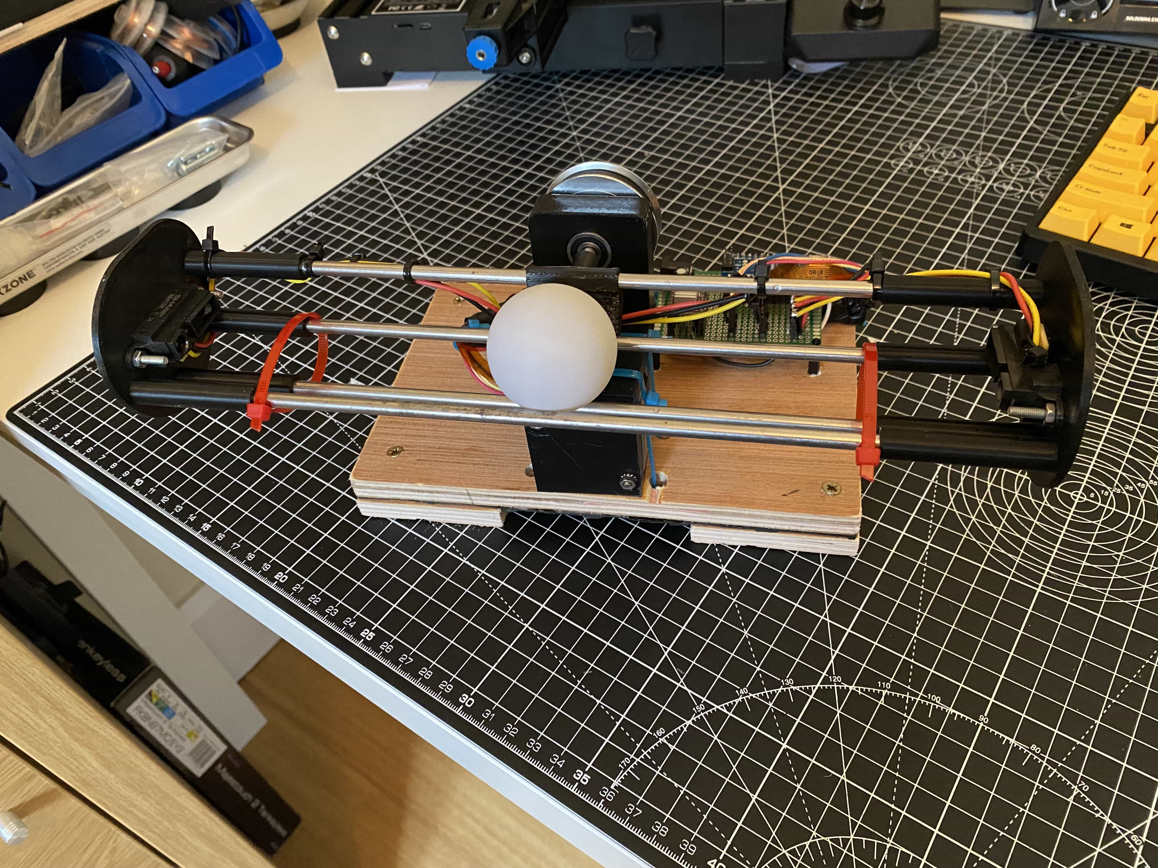
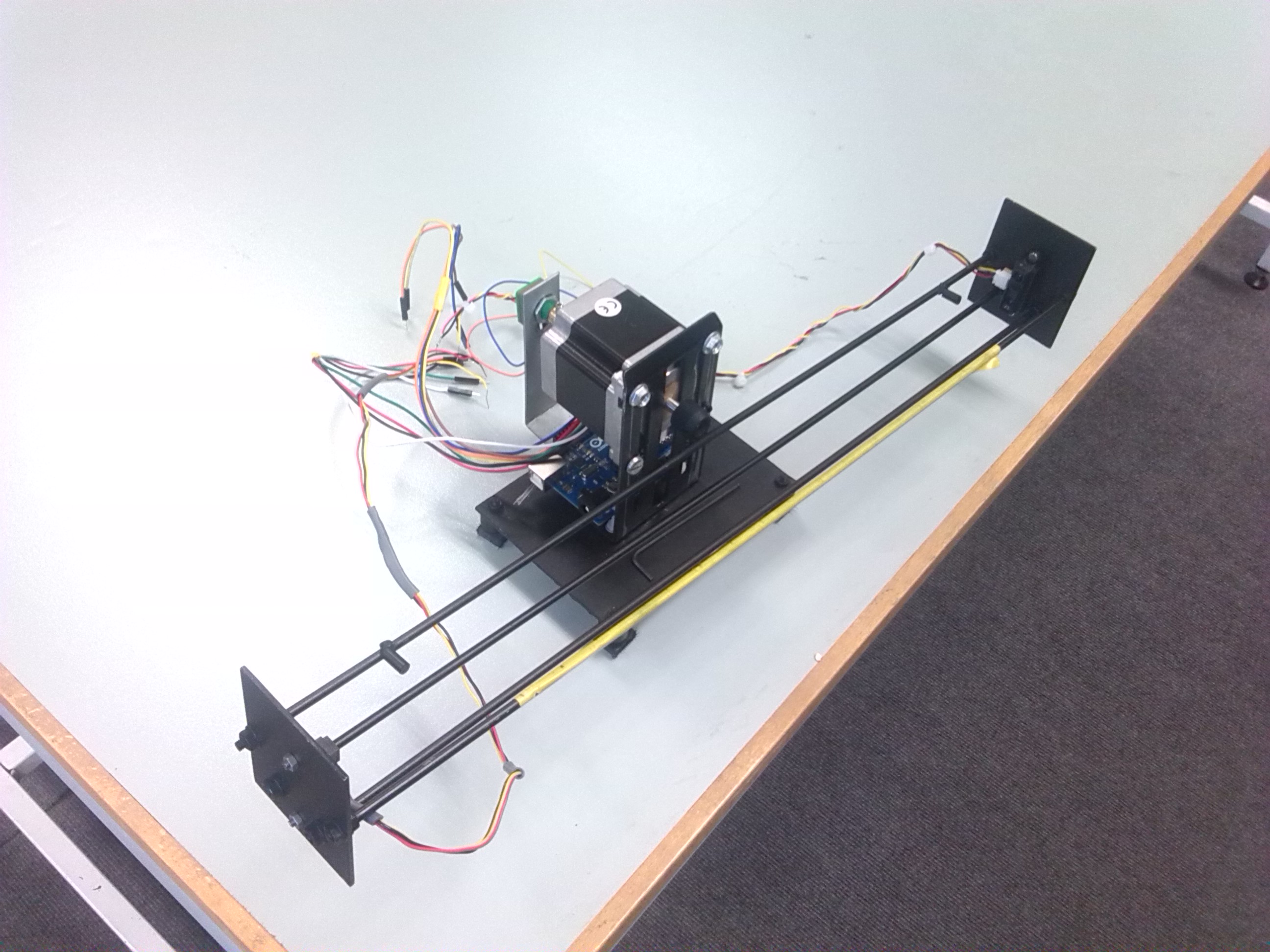
With that out of the way... Let's talk about some more of the mechanics. In terms of design, this rig looks at a glance more or less the same as the original. Here is a picture of the original version in it's final form.
While the design is largely similar to the original, there are some key improvements made in the latest iteration. Firstly, the new design has a shorter beam which makes the dynamics a little simpler. Speeds and acceleration of the ball are reduced overall which means the rig doesn't have to compensate as quickly. The shorter beam length also helps with an interesting property related to the range of the sensors, I will talk about that more later. The original rig was also made entirely out of metal that I salvaged and assembled by hand. The frame and beam were a little on the heavy side and not very precise. The new rig is a lot more precise in it's construction due to being designed in CAD and having several 3d printed parts. This has also helped to reduce the weight a lot which means the motor doesn't have to work as hard. A quick note on the 3d printing; I'm not really going to get into the details of it here, the rig was printed on a Creality Ender 3 V2 using Creality's own brand PLA.
Going back to how hard the motor has to work, there is another example of where the new rig is far superior to the old one. In the old rig you will notice the beam is mounted directly onto the shaft of the stepper motor. Now, I'm not a mechanical engineer but, I'm fairly sure even back then I knew this wasn't an optimal design. I think I did it because it was going to be easy and quick. Also, by studying pure electronic engineering at the time, I didn't have access to the resources of my colleges machining facilities. I couldn't get the technicians to make anything that I designed, so I had to make everything myself by hand. In my new design, I was able to leverage the near unlimited physical forms that can be created by a 3d printer. With better tools at my disposal, I was able to design a system to mount the motor and transfer power to the main shaft via a belt and pulley system. You can see the new drive system design below.
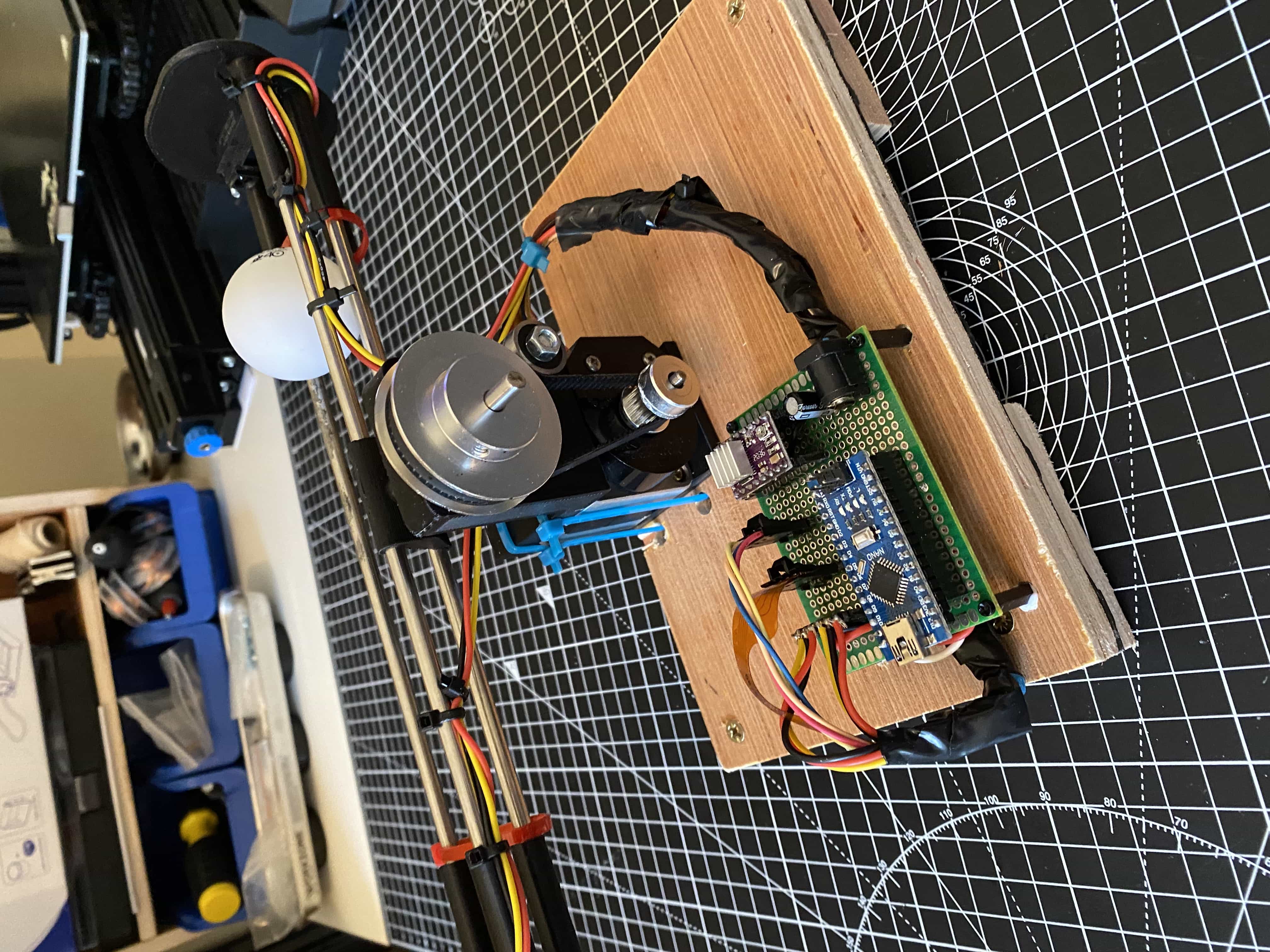
The drive system design was pretty fun for me, I had never designed with pulleys, belts, little 625RS bearings and drive shafts before. It's not perfect, but I think it's a lot better than the previous direct drive approach. The gearing from the pulleys reduced the load on the motor which is always a plus and also helped with fine adjustment of the beam angle with respect to motor position.
Before I finish talking about the mechanical design, I want to talk a little bit about tolerances. I am new to 3d printing, I think I have my printer well set up and in general I'm impressed with the parts it can turn out. As a tool, I'm delighted with it, but, there are always little tweaks to be made the first time I print something. One thing I have noticed is that holes in CAD often can end up being slightly undersized. This is a little annoying when trying to fit fixed sized real world part into, especially metal ones. I started to play with tolerances a little in this build to try make things compression fits. The bearings in the system are a very tight fit in their housing which is ideal. The end caps also fit nice and snug with a small bit of drilling to remove some excess material. I am sure I could get the prints better, however, for me, the 3d printer is a tool. I am reasonably confident in making things with it and I'm perfectly fine with having to do some post processing on parts.
The other part of the build where I ran into tolerance issues was in trying to slot some hardware shop bought "5mm" rod through the "5mm" internal diameter of the bearings I have. I'm not sure which to trust, they both more or less measured 5mm on my calipers (my money is on the bearings being the correct size). In any case, the shaft wouldn't fit. I don't own any machine tools, and I was loathed to introduce heat or forces into the tiny bearings by drilling them out. I needed to modify the shaft, but again, I don't have a lathe or anything to skim a tiny amount of material off of it. This is where I discovered a neat trick. I took the shaft, wrapped an end in tape and chucked it into my cordless drill. I pulled the trigger and then using fine grit sandpaper I polished the spinning shaft. After moving down in the paper grits and then using some wet sandpaper it got pretty smooth. I did this a few times checking the bearing fit each time, after only a few minutes I had a smooth fit. I then simply flipped the shaft around and repeated until it was perfect. Everyone might be aware of this trick already, but I thought it was great and was shocked at how well it worked. I was using stainless steal, so I really was just polishing up the surface and removing imperfections. If you were using aluminium, I'd say you could remove a surprising amount of material this way.
Electronics
The electronics of this rig might seem a little bit involved, but in general they aren't very complex. When I say that, I mean that the system is largely plumbing together a few parts to achieve the goal. There are no really complex circuits to have to try and break down. I will talk about each of the main components and give some background on them. The main parts of the system are as follows, an Arduino Nano microcontroller, a stepper motor, stepper motor driver, rotary optical encoder and two optical position sensors.
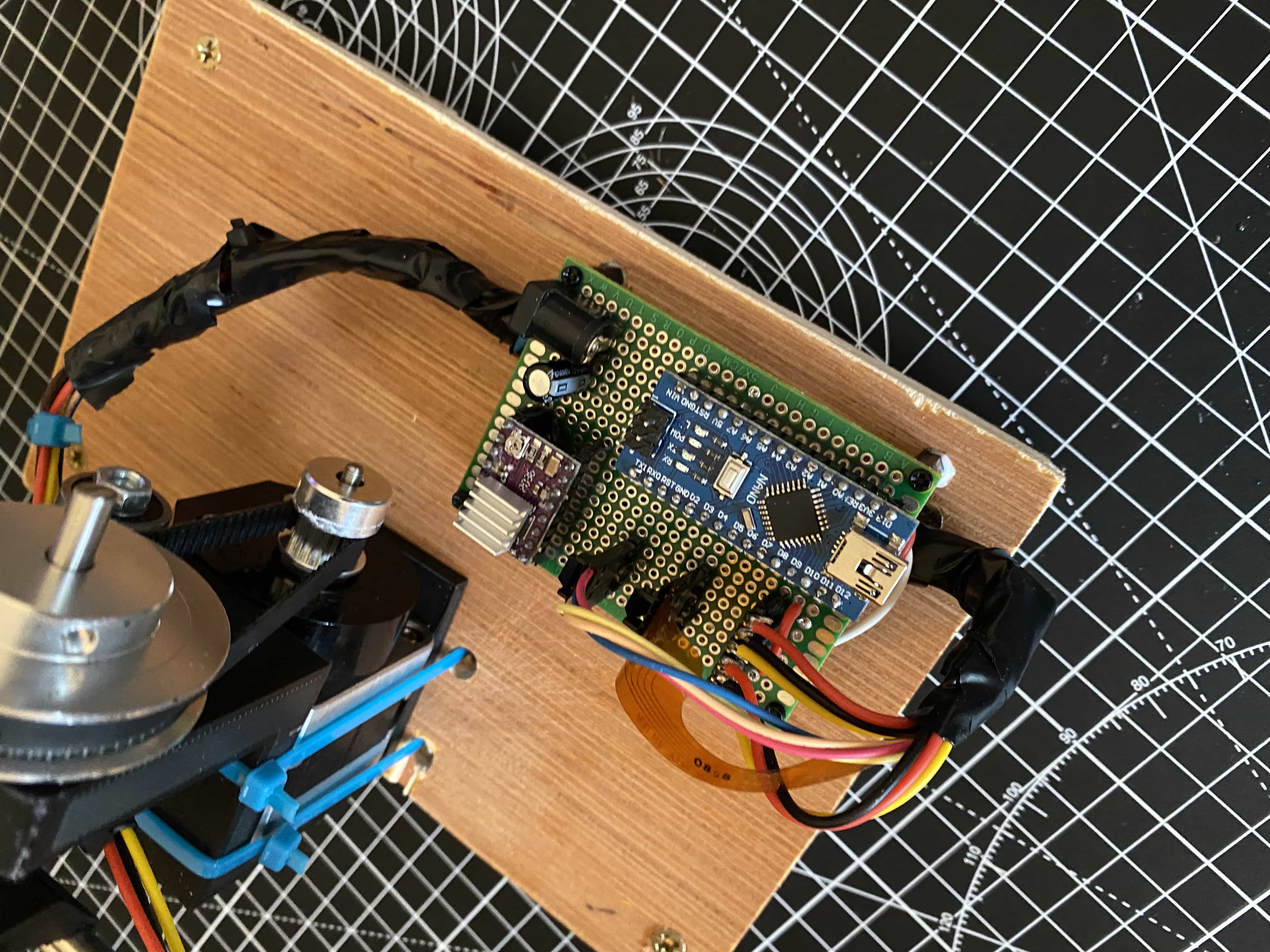
Lets start with the microcontroller, I'm not going to go into an real detail here about the Arduino as these devices are very common and are extremely well documented online. My choice for using it was simple, I had one lying around, I know how to write the software for one and they are really common, so I can share the code easily. One point to note, I decided to require the arduino to have it's own 5V power supply. Despite the fact that the system has a 12V supply, I decided not to step down this voltage to power the Arduino. Partly because I wanted to remove the need for more circuitry, but also I figured that you might mostly want to live plot the response of the system on your computer screen, so it made sense to just power it via USB.
For this next section I'm going to talk about the stepper motor and the stepper driver. A stepper motor is a special type of brushless DC motor that has the unique property of rotating in discrete steps instead of a smooth free rotation. This is achieved by puling the wires of the motor in a specific pattern. This pattern activates the coils such that their magnetic fields react with a small toothed rotor snapping it from one step position to the next. In this way the motor rotates at discrete increments. Often we talk about stepper motors in the number of steps per rotation or the number of degrees per step. For example a "200 step motor", takes 200 steps to complete a full revolution and has a "step angle" of 1.8 degrees. This means that each step rotates the shaft of the motor 1.8 degrees. The fact of a stepper motor needing to be pulsed to run means unlike other DC motors, you can't just plug it in and watch it spin. You need specific circuits to deliver pulses to each of the wires of the stepper in the correct order. This needs to be done with some sort of clock to control the rate of the steps and thus the speed of the motor. This is where our stepper driver (and microcontroller) comes in.
Stepper driver boards mainly implement a kind of circuit called a H-Bridge to provide the drive to the motor. They also contain the electronics needed to receive simple digital inputs in order to make the stepper step and change direction. These boards usually accept a wide range of motor supply voltages and commonly implement all the power electronics to handle the current requirements of the motor. It would be common to drive these with a higher voltage than your microcontroller, so usually you would decouple the motor drive from the rest of your digital circuitry. For this project I used a DRV8825 driver board, which is commonly used in 3d printers. The last thing I will say about this is don't ignore connecting the capacitor between the positive and negative lines of the 12V supply voltage. I ignored it in the docs because I didn't have the correct value of capacitor. I also then burned out two driver boards and had no idea what was going on... I stuck in a 22uF capacitor and it's been fine since! So, don't ignore it!!
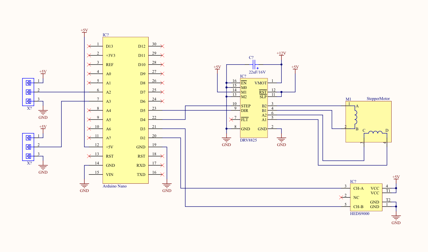
We have talked about steppers a bit now and before I talk about the optical rotary encoder I am going to take a short segue into some of the ideas of control theory just so that some terms I'll be using make sense. The beauty of stepper motors is as we said earlier, with each step, they move a fixed amount. Many hobbiest are familiar with steppers from the worlds of 3d printing and cnc machining. These machines typically employ stepper motors connected to screws, belts and pulleys to move around their work and/or tools. Anyone with a good knowledge of these machines will also know that typically aside from a couple of limit switches, there isn't usually anything else to tell the machine where it's tool or work is in space. In control theory, this is called "open loop control". Open loop control means that I tell something to do it and it just does it without me having to check. This is why steppers are so important to these kinds of machines, in theory, they can perfectly perform open loop control. This is great in theory, however, like everything else, steppers aren't perfect. Most of the time they can do a good job at open loop control, but if you need critical accuracy or you are operating the stepper to the limits of it's capabilities, you may "lose steps". This means the motor might not take exactly the amount of steps you want and might end up out of position. The compounding effect of this means the system could be come useless or it could break all together. Some things to consider here, are you using the correct drive current? Are you "microstepping"? How fast are you trying to drive the motor? (spoiler, they don't like to go very fast). With all that said, in order to ensure that our stepper is moving the correct amount, we need to implement what in control theory is called "feedback". Sometimes also called an "error signal", it is basically how far off the desired value (angle of the motor) we are. So if I tell my stepper to go 5 degrees, it goes to 3 degrees, my feedback error signal should tell me, 2 degrees. By adding something like this, our system is now called a "closed loop" system. One way to do this is to use a device called an optical rotary encoder. I should mention that for this project it would more than likely have worked without the feedback on the stepper position. However, the motor I was using happened to already have a HEDS-9000 encoder attached to it. I implemented it less as a requirement and more for fun.
Optical rotary encoders are really clever pieces of kit, they are also fairly expensive. Had my salvaged motor not happened to have one, I wouldn't have use one to be honest, but as a learning tool, they are worth explaining. They consist of two main parts, a body with a slot and a thin disk with precision cut slits in it. Inside the slot is a light source on one side and a light sensor on the other. The disk is mounted to the shaft of the motor and positioned so that it rotates inside the slot of the encoder. As the shaft turns, the disk with the slits rotates through the light source and sensor. This causes the device to output pulses. By counting the pulses and knowing how far apart the slits are, you can calculate through what angle the shaft has rotated. This may be a little hard to visualise, but if you want a really good explanation check out the information website for the encoder software library I used. This guy does a way better job explaining it than I do! Pay special attention to the interactive animation on the page.
The final part of the system to talk about are the optical position sensors. These sense the position of the ball and provide the overall feedback for the system. Earlier I talked about open loop and closed loop systems. When we think about systems, they can have many different loops depending on how we model it. In our system we have two loops. The motor loop or "inner loop" and the ball position loop or "outer loop". When we look at the outer loop, lets just forget about the inner loop, if it's doing it's job we assume it's working fine (in practice you need to independently verify that of course). The input for our outer loop is the angle of the beam. This should be intuitive as the angle of the beam causes the ball to change position along the beam. In this case, the feedback telling me the position of the ball is provided by two optical position sensors. The sensors I used were Sharp GP2Y0A41SK0F. These are very simple to wire, they don't need any software to run and are completely analog. Connect the 5V and ground pins on the sensor and the remaining third pin gives you a voltage between 0-5V representing the distance of an object from the sensor. The sensor uses an infra red beam from an LED to bounce light off of an object. A light sensor detects the returning light and induces a voltage which is proportional to the distance travelled. These sensors are great but they have some limitations. There is a deadzone of 4cm in front of the sensor in which you can't trust it's output. The sensor also only works to a max of 30-40cm, so the range is limited. These constraints aren't a massive issue for the system however it's worth highlighting a gotcha that got me in my previous attempt at using these sensors. Have a look at the below graph of the sensors response taken for it's datasheet.
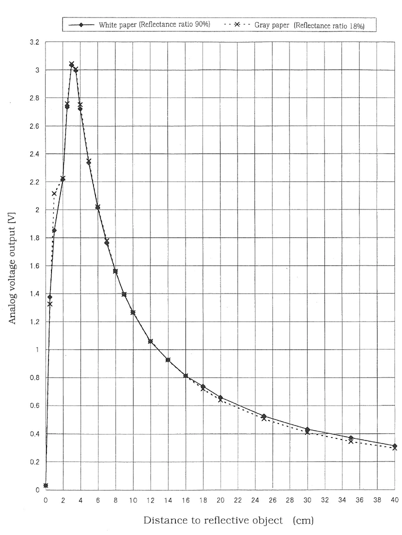
Firstly, you can clearly see the spurious reading at less than 3-4cm of distance that I mentioned earlier. It's not so much of a deadzone, the values just won't really mean anything. More importantly than the "deadzone", however, is the right side of the graph. During my first version of this system back in college, each sensor was being asked to detect the ball well into the far ranges of the sensors capabilities (the beam on the rig was longer than it is now). This meant that I was pushing the sensor into a highly non-linear operating region. This isn't too much of a problem, if you handle it correctly (which I did not back then). However, if you assume it's linear, you are in for trouble! This time around, I decided to get around the problem by making the beam shorter. In this way, the ball position largely falls along the approximately linear portion of the sensors response curve. I was able to just make this decision because, well, I can do what ever I want on this rig. In the real world however, it's critically important to understand the responses of sensors you are working with and handling them correctly.
Software & Control Theory
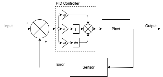
For the software used by the system, there isn't a huge amount to say, if you want to take a look at the code, you can find it here. The code is pretty easy to read and is well documented. Something that is worth digging into is something I have only just glossed over so far, the controller system. I discussed earlier on about open loop and closed loop systems. Here is how we normally draw these in terms of a system diagram.
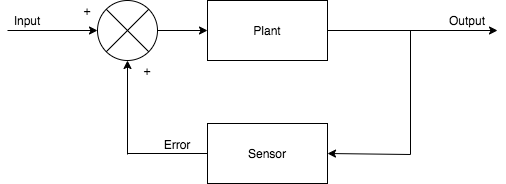
You will notice here that this system diagram simply takes the error that the sensors detect and sums it with the input signal and pushes it straight back to the "plant" (thing being controller). This type of system is called an uncompensated system because there is nothing there "compensating" for the error signal and telling the input to change in some way. This is a relatively dumb system and it would be highly unlikely that a system like this would be "stable". To make a system stable you generally need to implement some sort of compensator. There are loads of different types with different characteristics, however one of the most generic and widely used is a PID controller.
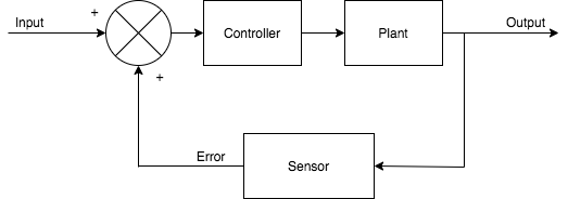
A PID controller is so named for the three ways in which it reacts to the error signal. Firstly, "P" is for proportional. This is simply a "gain" that the error signal is multiplied by. Higher proportional gain can makes systems have a more aggressive response or respond faster (faster does not always mean better). "I" stands for integral. This one is a little more complex, in this step the controller is summing the current error with past errors to create a response which will try to reduce what is called steady state error. Finally we have "D", this is for derivative. Here, the controller looks at the change in error signal with respect to the systems cycle time. This can dampen a system by reacting strongly to sudden changes in error values. Finally, there is a gain applied to each of these which defines by how much each of these contribute to the overall compensation when each part is summed before being fed into the plant. If the above doesn't make a lot of sense, that's okay! There is lots online around this topic, if you want to learn more, it's worth a google.
If you are into certain hobbies, such as flying quad copters, you may have heard the term "PID tuning" before. If you haven't, PID tuning is basically figuring out which combination of gain values for each part of the controller (labeled above as kp, ki and kd) gives the desired system response. PID tuning is almost an art form rather than a science and there are many methods for doing it. There are also loads of rules of thumb depending on what you are looking for out of your system. I'm not going to go into huge detail about the concepts of system responses and what these look like. If you are interested, do a google and have a read of some stuff around "overshoot", "settling time" and "steady state error".
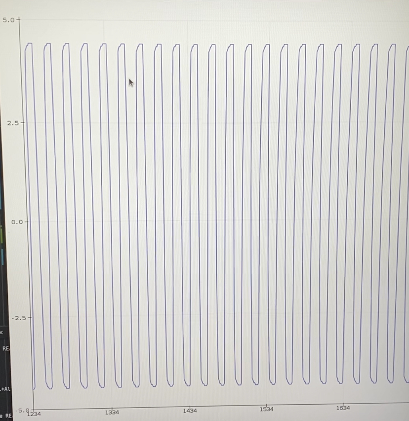
Instead of a deep dive into the theory of these I'm going to talk a little more intuitively about how you might see the effects of tuning these parameters on the ball and beam system. Firstly let's consider the basic operation of the rig. We place the ball onto the centre of the beam with the beam level. At this point, the ball should be stationary, and shouldn't for any reason move and the system should not move. Lets assume the feedback loop is going to give us the ball position as a positive or negative number telling us how far in millimeters the ball is from the centre of the beam. Let's also assume that the input to the system is going to be the angle that the motor should move to in degrees. Going back to our system now, lets say we are at an error of 0 (ball in the middle, not moving), we flick the ball and it moves 20mm to the left. The error signal feeds back to the input as -20. If I put that value into the stepper motor as -20 degrees, that's going to tell me to move the beam almost all the way as far as it can go on one side... That seems a little extreme doesn't it? So what if the ball moves 40mm instead? The rig can't physically move that many degrees. So what do we do? This is where our first PID tuning gain coming in. We are probably going to scale this down using our kp gain. If we made kp something like 0.25. Then we could scale down those dramatic angle changes to be a bit smaller and make our system respond more sensibly. At this point we are leaving our ki and kd gains at 0. All we are concerned with is adjusting the kp gain up and down. There are some systems that you can make reach stability with just a kp gain. However, most complex system will require tuning the other parameters. Typically we want to tune the kp gain until we get to a nice stable oscillation. You can see what that might look like below with a system output logged from the rig via the Arduino serial plotter.
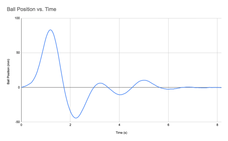
This is pretty, but it doesn't help us balance the ball around the centre point really. To achieve this we need to start modifying the ki and kd gains. For this system, the ball is very light, so it rolls very fast at a small incline. This means it will have a tendency to want to take off very fast when the beam moves. To compensate for this we are going to want to add in some kd gain to help correct for fast changes. However, the ball will also want to rock back and forth around the centre point if we respond to sharply. To help this we want to reduce the steady state error by increasing the ki gain. I can't really tell you what values to use for this as it depends on so many factors including what kind of response you want your system to have. One tip I will give is, small changes can make a HUGE difference. Try different orders of magnitude of jumps in value, start small and work up. This is largely trial and error and a certain amount of intuition. Below you can see a sample system output correcting for a balanced ball being flicked and then returning to stable again.
Back when I did my final year project I had a really good understanding of the theory behind all of this. I had built many different computer simulations in Matlab to help design the controller and test my system before actually running it. However, at that time, the part I really struggled with was how do I actually code the controller on my Arduino? Unfortunately, the practical side of how you might do this in the real world wasn't really taught to us in college. I can't blame the university, they were teaching us the foundational background theory. In the real world, this could be done in hundreds or ways, it wouldn't make sense to teach us a specific one. However, it ended up being something I really struggled with during the project. Step forward many years and I have discovered that I was massively over complicating things. The implementation of a PID controller in pretty much any programming language is actually really simple. I'm not going to go into much detail, but this is pretty much all it takes!
Design Limitations
I set out to rebuild my final year project, more or less the same way as it was originally designed. Aside from a few tweaks which have made it function better, the overall design is pretty much the same. While the machine works, I think there are some changes to the design that could really improve it. I'm going to talk about two of them, one being the ball position sensors and the other being the overall mechanical design.
After some fairly aggressive filtering, some clever limiting of the range on the sensor and some offset tuning; I managed to get some decent values from the sensors. Even still, the sensors seemed to have some issues. Firstly, they are pretty noisy. Interestingly, the noise is worst when the ball is stationary, while moving, the sensors give some nice readings. When the ball settles down to almost stationary, the sensors start to show up some pretty annoying noise. With PID controllers that implement a relatively high "D" gain, noise is the enemy, and can lead to the system kicking off into oscillations without any input. Not idea in this case as the ball is meant to settle down and sit still. This is partly what lead to aggressive filtering to try clean up this noise. Another issues with the sensors is that they happen to be sensitive to ambient light. This one is a bit more anecdotal on my part, but I noticed that the system would respond differently in dimly or brightly lit room. The final issues are the relatively short linear region in the response and limited overall range. All in all, they are fine for what they are and I've managed to make them work. However, I think with different sensors, the system could be better. There are more complex ultrasonic devices which offer better performance which might be better for this application, especially if you wanted to scale up the size of the rig.
The final thing I think could be better is the general mechanical design. The design was based around the beam being supported at it's centre point and tipping side to side around this point. This has the effect that to change direction there is a fair amount of torque required to shift the entire beam around the centre point. This design is also unlikely to scale very well due to the increase in the moment of inertia about the drive shaft as the mass of the beam increases. This design is also some what limited in terms of it's actuation, you are more or less limited to a motor or servo to provide rotational actuation to the rig. What might possibly be a better design would be a beam with a pivot on one end and at the other end, an actuator. With the entire beam acting as a lever, the amount of torque would be greatly reduced. Changing the actuation point also means that the mechanism now becomes a vertical offset which could use a linear actuator for control (or a servo, eccentric cam or motor). In any case, the options for the drive are a bit more varied and might end up giving more favorable results. This system could also scale up much easier by reducing the torque requirements.
What's Next?
For this exact machine, possibly not much. I set out to rebuild the machine and make it work. With that basic brief done I don't think I am going to do much more with the rig I built. I might live on a shelf as a working display piece. I might spend some time writing an computer application for interfacing with it and controlling it so that it could be used as a teaching tool for control theory. I am also considering putting everything together as a DIY kit when you maybe buy a box of parts and 3d print some others. I have no idea where to even start with that, but I think it could be fun... If you know how to do that, please get in touch!! Regardless of what comes next, the knowledge I picked up working on this I will definitely bring to future projects and the confidence boost will keep feeding my ambitions!
Finally, here is a link to all the tech specs, designs and code!
Keep on making things! - IanIf you enjoyed reading this article and would like to help funding future content, please consider supporting my work on Patreon.