Quick Builds #2
8th Nov 2021
Making Things 3D Printing Electronics IKEA HackingWelcome! Today I'm going to talk about a few smaller projects I've done over the past few months. Firstly we are going to talk about a massively over engineered desk fan, then we will talk about a custom built USB force plate I built and finally some IKEA hacking I did. Enjoy folks!
As always, if you like this content and would like to support me making more of it, you can help me out over on the Patreon page.
Desk Fan
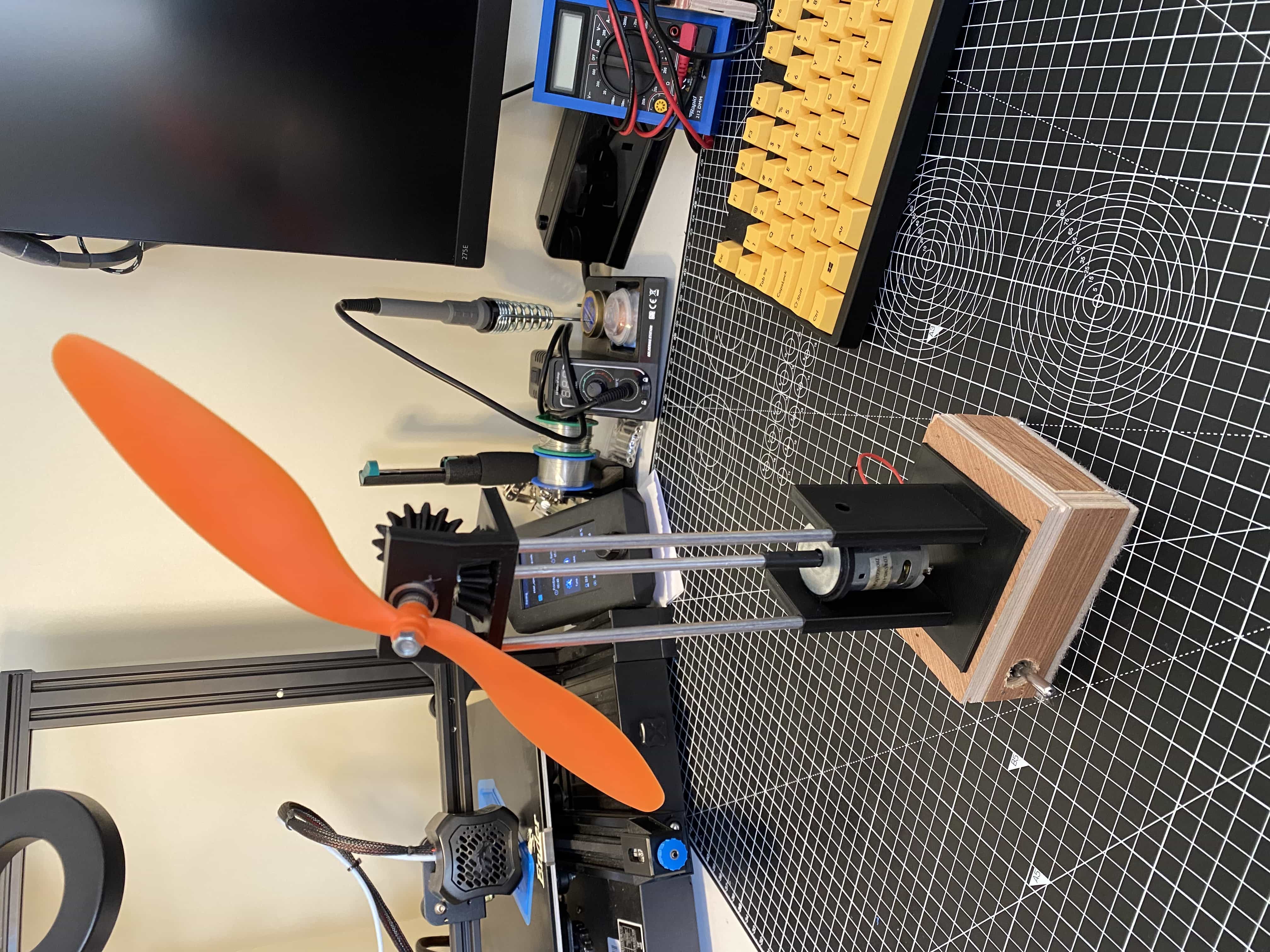
I happened to have a load of model aeroplane props lying around from when I first started my drone project. I didn't know what I was doing and bought a load of random props online... Almost all of which turned out not to be suitable. So, being the good guy that I am, I offered to give them away free online. No one happened to want them, but there was one response from a friend of mine making some joke about me having loads of "fans" after giving them away. To spite him, I decided to design a massively over engineered desk fan out of one of the props and an old DC motor I had lying around.
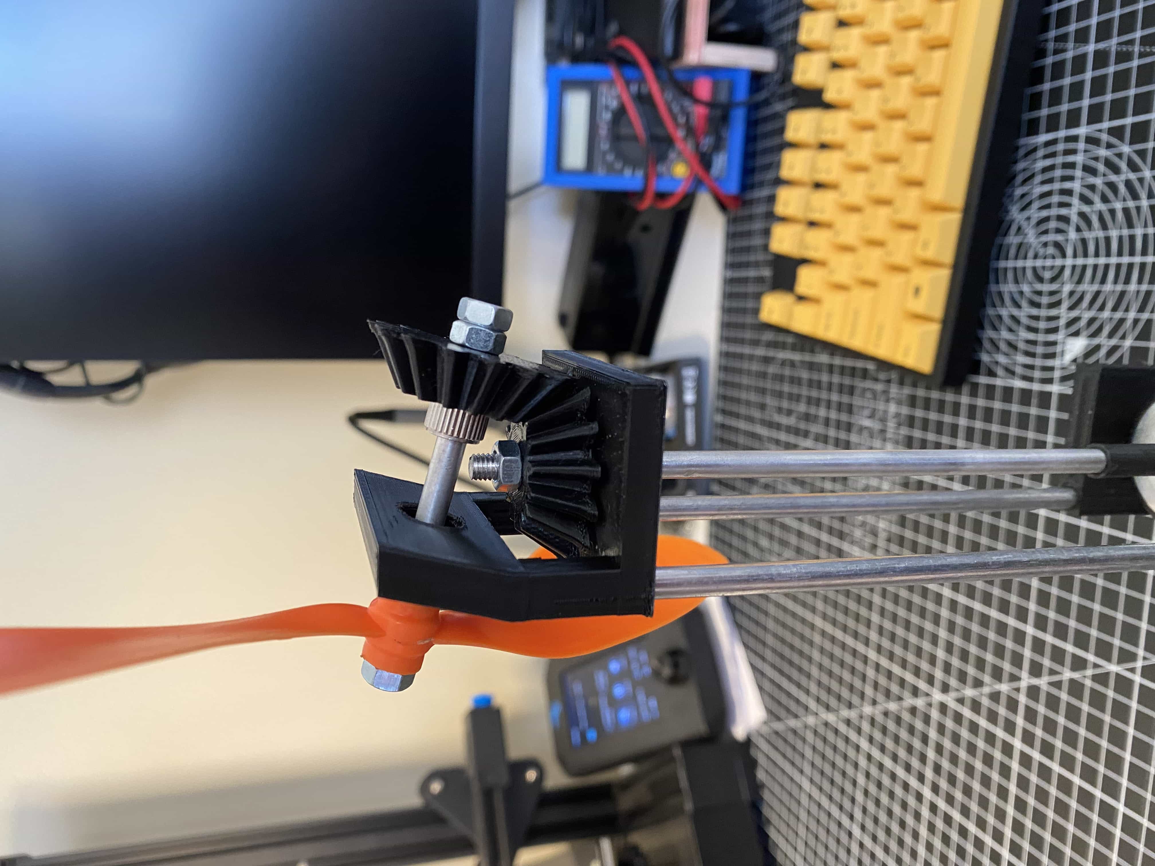
Despite the project being born out of spite, I actually had a lot of fun making it. I knew I wanted to make some sort of elaborate mechanical linkage, I also wanted to transfer the power over a large distance to show off the moving parts (i.e I wanted it all as exposed and dangerous and impractical as possible). I had some aluminium rods lying around, some bearings and of course my trusty 3D printer. The design was all pretty straight forward but I got to play with some stuff I have never touched before; 3D printing gears. Not only simple gears but bevel gears, which I have also never designed! I used a great FreeCAD plugin for designing gears to create the 3D models. I was pretty happy that I was able to design the gears to have a slight angle to tilt the fan up a little. I think it looks cool and also added some more complexity to the shaft mount to get the angle correct. This was a fun little problem to solve.
Force Plate
A few months ago I saw a pet food bowl in Aldi with a built in weighting scales. In an effort for our cat Kimchi to not become a fat overfed monster, we weigh out her food for each meal. A food bowl with a built in scales seemed like a good idea. The problems started almost straight away... Firstly, the scales required 4 AA batteries, WTF??? I have a kitchen scales that uses a single CR225 button battery that has never been replaced in more than 4 years. Getting over this, I started using the scales... More problems ensued. Firstly the LCD screen on it could hardly be read, it was really dim so was useless in daylight. I then went to use it the day after I bought it and it started giving me a low battery warning...WTF?? I also noticed later that evening, that you seem to have to manually turn off the scales after use or it seems to sit in some sort of standby mode. With the lights turned off at night, I noticed a tiny flashing light behind the LCD panel on it... more, WTF?? Anyway, after the batteries dying, I decided this thing was useless and was going to throw it out. However, I decided to take it apart and see what was going on inside... This is where things got even weirder. I inspected the circuit board only to find a BLE chip and antenna traced onto the board!! Why on earth does this pet food bowl need bluetooth?!?! No wonder the batteries didn't last pissing time. What's weirder, no where on the box or instructions did this say it was bluetooth enabled... So anyway, this is all a long way of saying, I took the load cell out of a crap weighting scales and decided to do something with it!
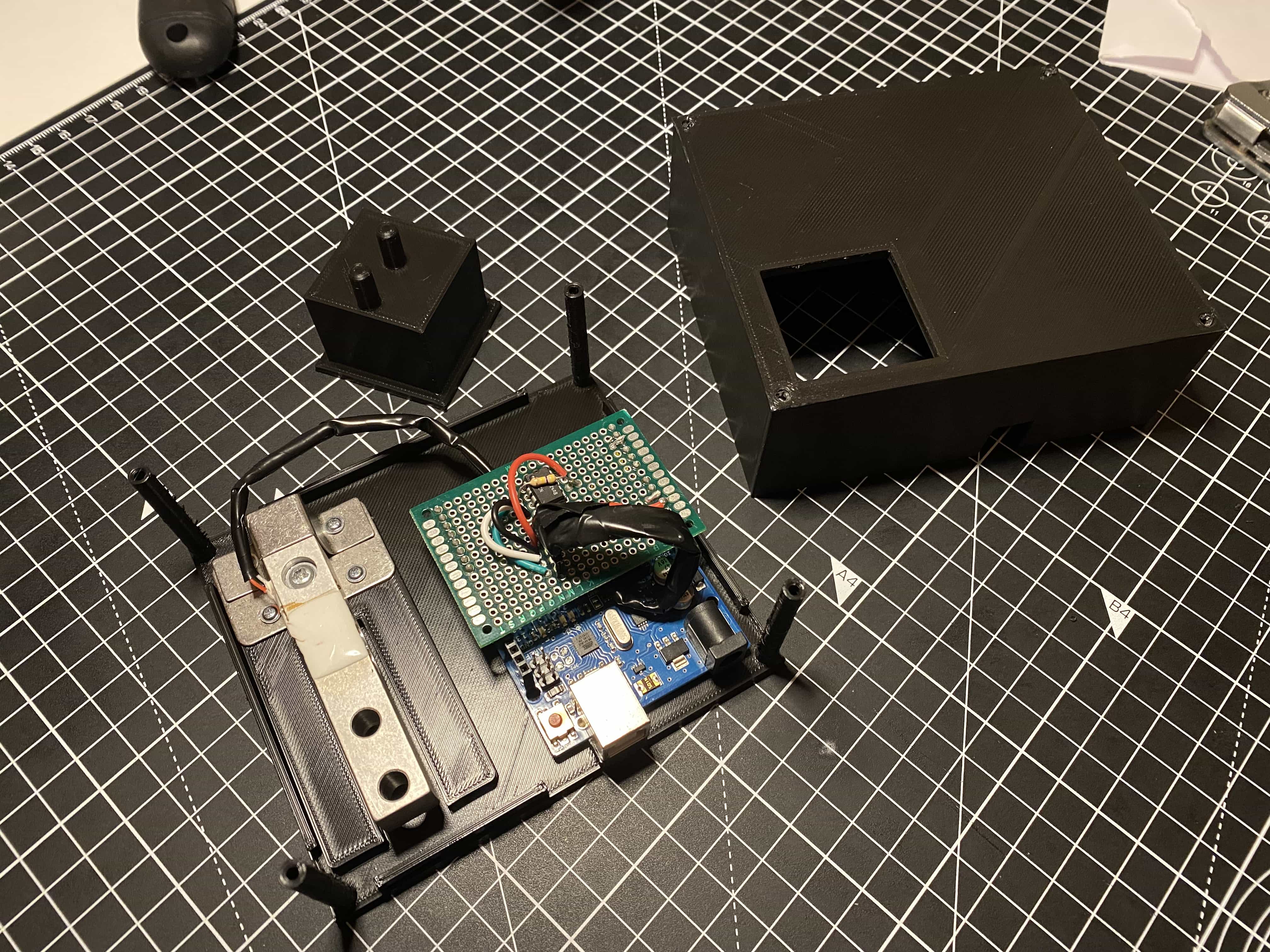
Load cells are pretty interesting pieces of kit. They are basically a stiff metal bar with embedded conductors connected in what is called a Wheatstone Bridge arrangement. The specific mechanical design of the load cell means that when a bending force is applied to it, the resistances of the conductors change triggering a voltage change across the bridge, neat! I had never played with a load cell before, but I knew enough to know that I wouldn't be able to just connect it's outputs to a microcontroller and get a reading. I would need something called a differential amplifier. Basically an analogue circuit capable of detecting a small difference in the output of the bridge and amplifying it to a level my microcontroller could detect. In real life, there are fancy instrumentation amplifiers designed for this kind of job, but I decided to just use what I had on hand. I built a simple op-amp circuit with feedback using an LM741CN op-amp I had lying around.
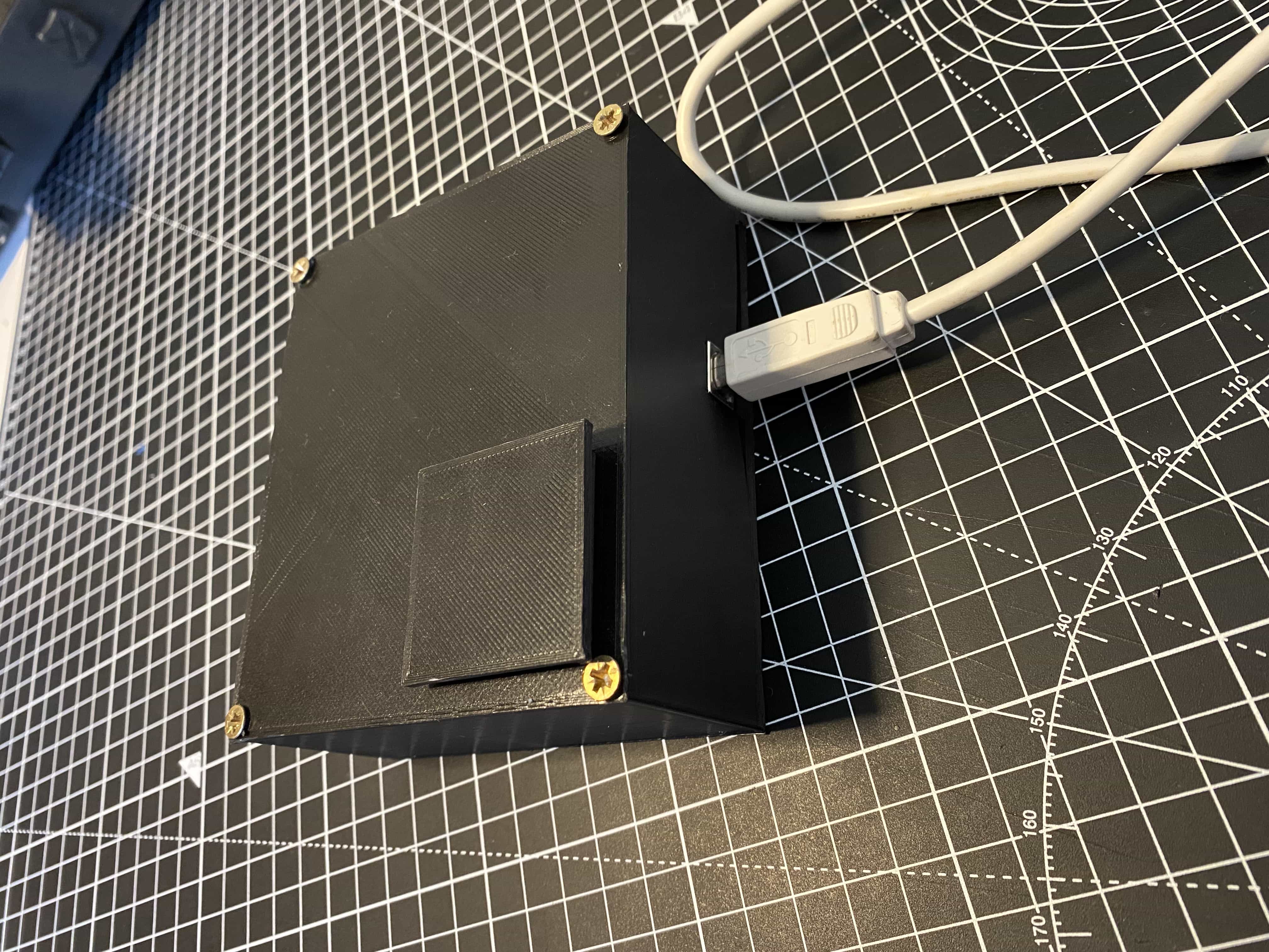
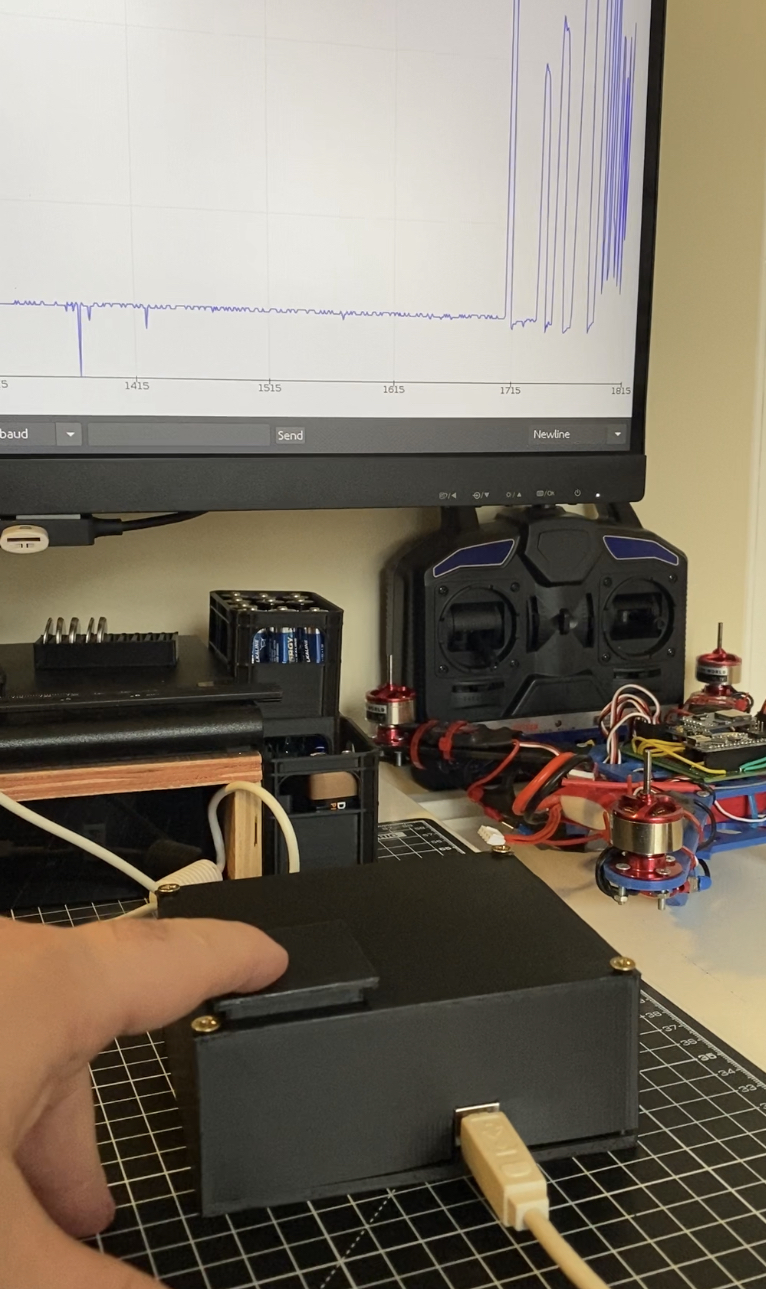
I also put the whole thing in a 3D printed box with a little plate connected to a plunger that interfaces with the load cell. Fun fact this was the first 3D printed box I ever designed... That's not really important... just popped into my head. The final step was to write some simple arduino code to read the analogue voltage and parse it into a sensible numerical scale. You can see below the output you can get while pressing the force plate while it's connected via USB to the Arduino serial plotter.
IKEA Hacking
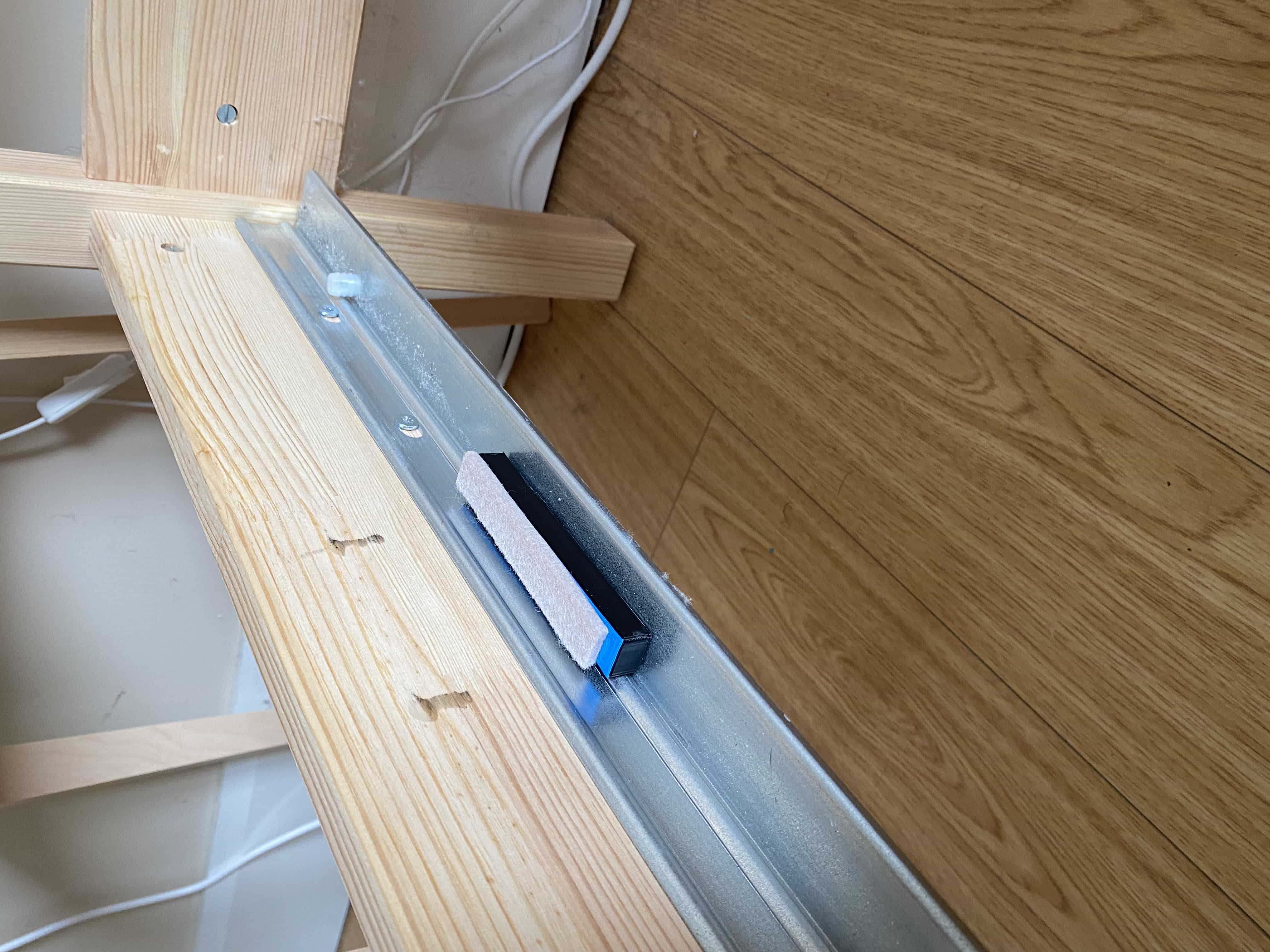
I've had an IKEA bed for a while now, around 8 months. To de specific it's a Tarva standard king size. We decided to get the Lonset slats for it because they were meant to be better than the standard ones and the whole assembly requires a metal centre beam called a Skorva. At first the bed was great, nice and solid and didn't creak or anything. However, after a few months it started to make some noise. I first went around and tightened up all the fixtures, but it still creaked. Next, I noticed that the Lonset slats frame would move a bit and was making noise off the bed frame. I decided to stuff some cardboard in to the gaps, and this worked... for a while. Eventually the cardboard compressed enough and just slipped out. By this time I also realised that the Lonset frame itself was bending hugely and making one side of the bed sag a lot. I noticed that the Lonset frame is only supported at each end on the frame with some tiny little risers. So I decided to 3D print some adapter pieces that mount to the frame and midbeam to support the slats better. This has since taken out all the noise from the bed and made it much more ridged and firmer. The bed no longer creaks and it doesn't sag either!
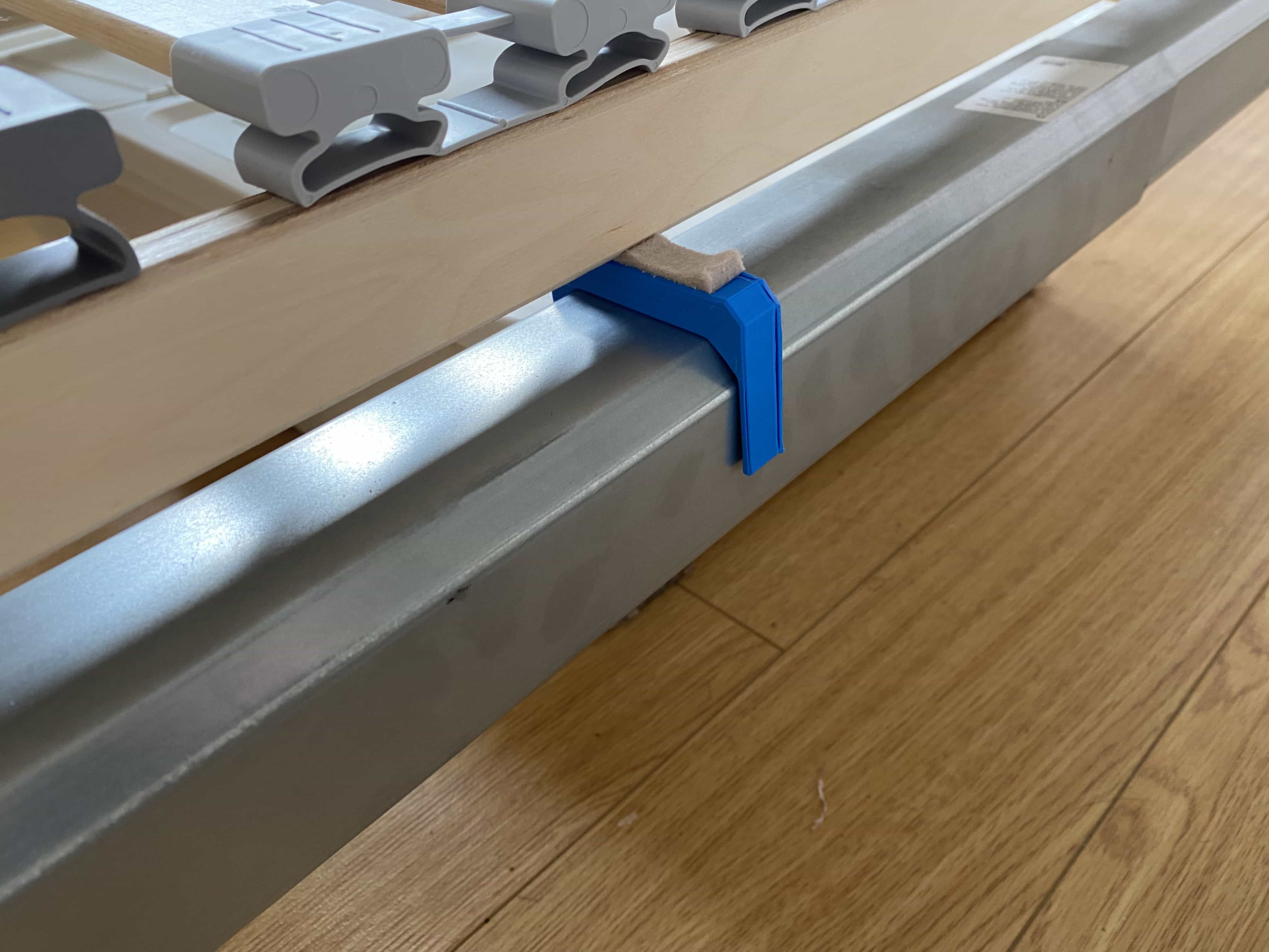
It was all pretty striaght forward, the side risers were designed to be screwed into the frame using some self tapping screws while the midbeam supports just slot over this part. This is important as the midbeam itself is telescoping so I didn't want to end up putting screws into it. Finally, the last step was to stick some felt pads onto the plastic parts. This helps keep down noise and has made the parts settle into a nice snug padded fit.
What's Next?
I recently bought my first table saw! It is the kind that is meant to sit on a worktop, so I will possibly be making a movable cart/table for it to sit on. On the theme of sheds, I am also in the process of designing a cyclone vacuum system for the shed, so that is also on the books!
Keep on making things! - IanIf you enjoyed reading this article and would like to help funding future content, please consider supporting my work on Patreon.