Building a Drone - Part 1
28th October 2021
Making Things Electronics 3D Printing Drone QuadcopterA few years ago I was living in a tiny two room basement apartment in Dublin (before you ask, yes, yes it was depressing). I was out of college a few years and working in software. I got thinking that I hadn't been using my background in electronics at all and that I should pick up a hobby project in that area. I settled on trying to build my own quadcopter drone. Myself and a friend of mine started doing some work on the project but time, money, space and supplies were all an issue. The project ended up being abandoned for many years.
Fast forward to the middle of COVID lock down, I find myself with an abundance of time on my hands, I now live in a space where I have plenty of room to build things and I had just bought a 3D printer. Aside from playing with small prints, I wanted a bigger longer running project to use it with. Ideally, this project would also satisfy my passions for combining mechanics, electronics and programming. With all those factors, I decided to resurrect the quadcopter project. This time I had the space, time and a fun new tool to build it with!
In the first in this series article I'm going to talk about the flight mechanics of a quadcopter, as well as my mechanical design, and how I went about designing and 3d printing the airframe. Later in the article I'll also talk about component choices around props, motors and batteries. In later articles I'll talk about the electronics, software and control theory behind the quad in detail.
The TL;DR
Sorry, no cheating with this one, the fun is in the reading!
Quadcopter Mechanics 101
When you dig deeply into the flight mechanics of quadcopters you really end up in a big ol' mess of linear algebra and inertial reference frames... For the seasoned engineer, this is fine, however, for the rest of us; we don't need that negativity in our lives. Have no fear, I'm going to attempt to build intuition for how these machines fly without any maths. I'll also introduce some terminology that will be helpful later regarding how we talk about their movement in different directions.
Quadcopters, like helicopters are an interesting class of aircraft that aren't inherently aerodynamic. That is to say, if you shut off all the engines, the craft will not glide for any real amount of time. A quadcopter will drop out of the sky like a stone if it's engines fail. From working on my own quadcopter I can say they really do fail in spectacular ways. As a side note, I'm glad that these aren't built at human scale because riding one would be utterly terrifying... also, I have come to appreciate that a helicopter is a PURE DEATH MACHINE. With that outburst out of the way, how does a quadcopter fly?
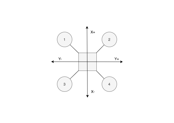
A quadcopter has four sets of rotors that when spun create thrust which lifts the quad. Once the spinning rotors generate enough thrust (equal to the weight of the quad) the quad will lift off the ground. Just making it lift off the ground is relatively simple, keeping the quad stationary and balanced in the air is where it gets more challenging. To describe this, we will define three axes of movement, x, y, and z. If you were to look directly down at the top of a quadcopter, you would see it's airframe and four motors like below. In this plane, we will notate the x and y axes as shown. While flying and hovering "level", this x-y plane will be perpendicular to the earth. Imagine an ideal model, the quadcopter is perfectly balanced, all the motors equally powerful and efficient, there is no wind, and all the motors are running at the same speed. In this model, the forces across the entire x-y plane are equal and the quadcopter will hover perfectly level to the earth.
Quadcopters are also interesting as far as aircraft go as they do not require the manipulation of any kind of aerofoils to move them around as they fly. An airplane uses ailerons to adjust airflow over it's wings to perform maneuvers. Even in a helicopter the rotor assembly is moved relative to the body of the helicopter to allow it to move around. With quadcopters, there are no aerofoils that move and the rotors remain in a fixed orientation. This lack of moving parts makes them mechanically simple but also means they depend entirely on advanced motor control to fly. If you consider model planes and helicopters, they don't require onboard computers to fly. However, all quadcopters require onboard computers to fly.
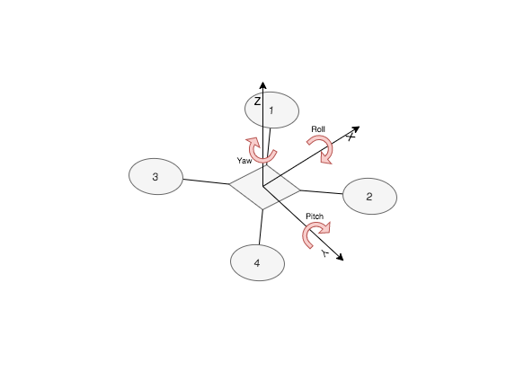
Before we continue I want to introduce a new concept, "principal axes". The concept of principal axes introduces three new terms - pitch, roll, and yaw. Together with our x-y-z coordinates, these values describe how any craft traveles in a medium (air, water, space, etc.). The values of pitch, roll, and yaw are the angle a craft makes around each of the principal axes x-y-z.
In our diagram above, imagine the quad rotates around the Y axis so that motors 1 and 2 are pointing down towards the ground and 3 and 4 up towards the sky. In this case we would say the pitch has gone negative as the craft rotated nose down towards the ground. If the nose lifts up that is positive pitch. We can picture the same with the X axis. As it rotates around this axis we say it moves between positive and negative roll. If the quad tips to the right, roll is negative, if it tips to the left, roll is positive. The main goal with stable level hovering is to keep the angles of roll and pitch at 0. Finally, we have yaw, I'll talk more about yaw in a later article when we discuss sensors and control theory. For now, just know it basically describes the "forward" direction of the quad. While flying level, the angle of the abstract "front/nose" of the quad is defined by the angle of yaw, or the rotation around the Z axis. This tells us what way the quad is "pointing".
Now that we have a common language with which to discuss how a quadcopter moves, let's talk about HOW it moves. Let's start with the easiest thing to consider on it's own, forwards and backwards. Remember, for our quad, we can't move the angle of the rotors and we have no aerofoils to steer with. The way in which we move forwards and backwards (movement along the X-axis) is by rotating the quad around the Y-axis, i.e changing the value of the pitch angle. Imagine we are hovering level and we change this angle to be slightly negative ("nose" pointing down). Some of the thrust keeping the quad aloft is now being sent backwards along the negative X direction and so the quad will move forwards along the positive X direction (and possibly lose a tiny bit of altitude). The same rule applies in reverse for going backwards. If you are noticing the pattern, the same rules again apply for moving right and left. By changing the roll angle around the X-axis, the quad will move left and right.
Previously we said that we "adjust" the roll and pitch angles to make the quad move around. While this is the mechanic that will make it move, how do we actually "adjust" these angles? We said earlier that assuming an ideal system, once all the motors are running at the same power the quad will hover level to the ground. As we don't have aerofoils and our rotors are fixed, the only thing we can change is the speed of each motor. By changing the speed of an individual motor, we change the amount of lift that is being contributed to the overall thrust of the quad. Referring back to our earlier diagram, you can see that around our pitch and roll axes, we have an equal number of equally spaced rotors. If we want to change the pitch angle to move the quad forward along the X-axis, we need to reduce the thrust of motors 1 and 2 at the same time and increase the thrust of motors 3 and 4. The question then becomes by how much do we reduce the speed of one set and increase the speed of the other set? Ultimately, the overall thrust needs to stay the same, or else the quad will start to drop out of the sky. The simple and easy thing to do is to reduce the thrust of one set of motors by the same amount as we increase the other set.
However, there is an issue with the above approach. If you vastly increase the speed of one set of motors and decrease the other, you will get a dramatic change in roll or pitch angle. If the angle is large, a lot of the thrust is now going to point in the direction of motion and away from the ground. If this happens, the lift of the quad will be dramatically reduced and the quad will fall very quickly. One approach here could be to make very small adjustments to pitch and roll. This would make the loss in vertical thrust smaller and possibly negligible. However, this will also make the quad slower to move around. A more advanced approach might be to compensating for the loss in thrust by increasing the power to all motors slightly while manoeuvering. While this will prevent the quad losing altitude while manoeuvering, it adds complexity and could make manoeuvering twitchy. As with many things there is a trade off to be made. What is your use case? Do you want a very fast and sensitive racing quadcopter? Or do you want a slow and stable one for doing arial photography?
Motors, Props & Batteries
This next section could really be an entire series of articles on it's own. I'm not going to go into huge details around choosing the exact best choices for your application. Instead I'm going to try outline a rough thought process for picking motors, props, batteries, and their impact on your design. Later on in the article I'll show my airframe design and talk about some learnings I've made from it and how it was informed by the choice of props and motors etc.
Firstly, we need to think about roughly how big we want the to quad to be. We can do this first process as sort of a t-shirt size estimate. Should it fit in the palm of my hand? Should it fit on an A4 piece of paper? Or should it be bigger? Depending on what you want to use it for, the size requirements will change. Remember, the larger you go, the bigger the props, the faster things will need to spin and the more dangerous they will be. Over a certain size it's far too dangerous to fly a quadcopter indoors. Personally, I wouldn't want to fly any quad that was much bigger than 15-20cm inside my house. If you want just a little toy to fly around your living room, think palm of your hand sized. It would probably get thrown around in the wind outdoors, but it will be less dangerous and probably won't break anything if you crash it inside the house. If you want something for lets say areal photography, you probably want to think about something one foot or more across. At that size, it is going to be pretty heavy, and it's going to have large props spinning very fast. You don't want to fly it inside, crashing this could result in serious injury or property damage.
With the rough size picked out and an idea of what you want to use the quad for, we need to pick motors and props. It's worth considering that the more weight you want to lift, the larger the props you will need. Larger props require more torque to spin them. More torque means your motors will draw more current. More current means a beefier battery capable of having lots of current drawn from it. Beefier batteries are of course heavier... Can you see where this is going? With these trades offs in mind, you need to design your quad to be as light as possible to offset the weight of the batteries, controllers and motors themselves. Most high power motors these days used in hobby radio control are very light and the electronics are also not very heavy. The battery is going to be the single heaviest piece of the design.
Weight is easier to add than to take away and having some excess power there will give you more freedom in your design. That is to say, an easy way to start is by picking a combination of props and motors to give you more thrust than you think you need. There are online calculators for this, you can plug in estimated numbers for the weight of your quad and go from there. Typically you will pick a set of props by their diameter. This will probably inform the size of the quad or vice versa if you already have a limit to the footprint of the quad you want.
Up to now, I have kind of hand waved over motors and batteries. This can be a bit complicated so I'm going to spend more time talking about it in detail. The only motor you are going to use for a quad is a brushless DC motor. Modern brushless DC motors are incredible. They are tiny, light weight and capable of spinning at very high RPM. The motors I am currently using for my quad have a RPM motor constant value of 1200Kv. This value, when multiplied by the motor voltage (11.1V), gives an estimated top speed of 13,000 RPM, that is quick! If you are already feeling a little confused, don't worry! These numbers can start to become confusing, however keep in mind, most motors will come with a recommended size of propeller to use and their operating voltages etc. These kind of motors are great, however, they have some trade offs. Firstly, they are fairly complicated to control. Unlike normal DC motors, these motors require their wires to be pulsed in a specific pattern and at a specific frequency. This pulsing pattern is how they manipulate the internal magnetic field which allows them to spin. For this reason, you need to match your motors with a proper electronic speed controller (ECS). The main job of the ECS is to take the power supply from your battery and deliver it to the motor in the correct pulsing pattern. The ECS will also control the speed of the motor based on a control signal input from either an RC receiver or a microcontroller. When you go to buy an ECS you will need to know the current requirements of your motors and your voltage. This brings me to the second draw back of brushless DC motors. They draw massive amounts of current. The motors I am using can draw up with 16A. If you think that does not sound like much, consider your average phone will draw less than 1A while charging. A single motor will draw 16 times as much as a phone charging and there are 4 motors. That's a massive amount of current. The first thing you need to make sure of is that your ECS can handle the current requirements of your motor. In my case, my ECS units are rated for 20-25A max, so the 16A from my motors is fine.
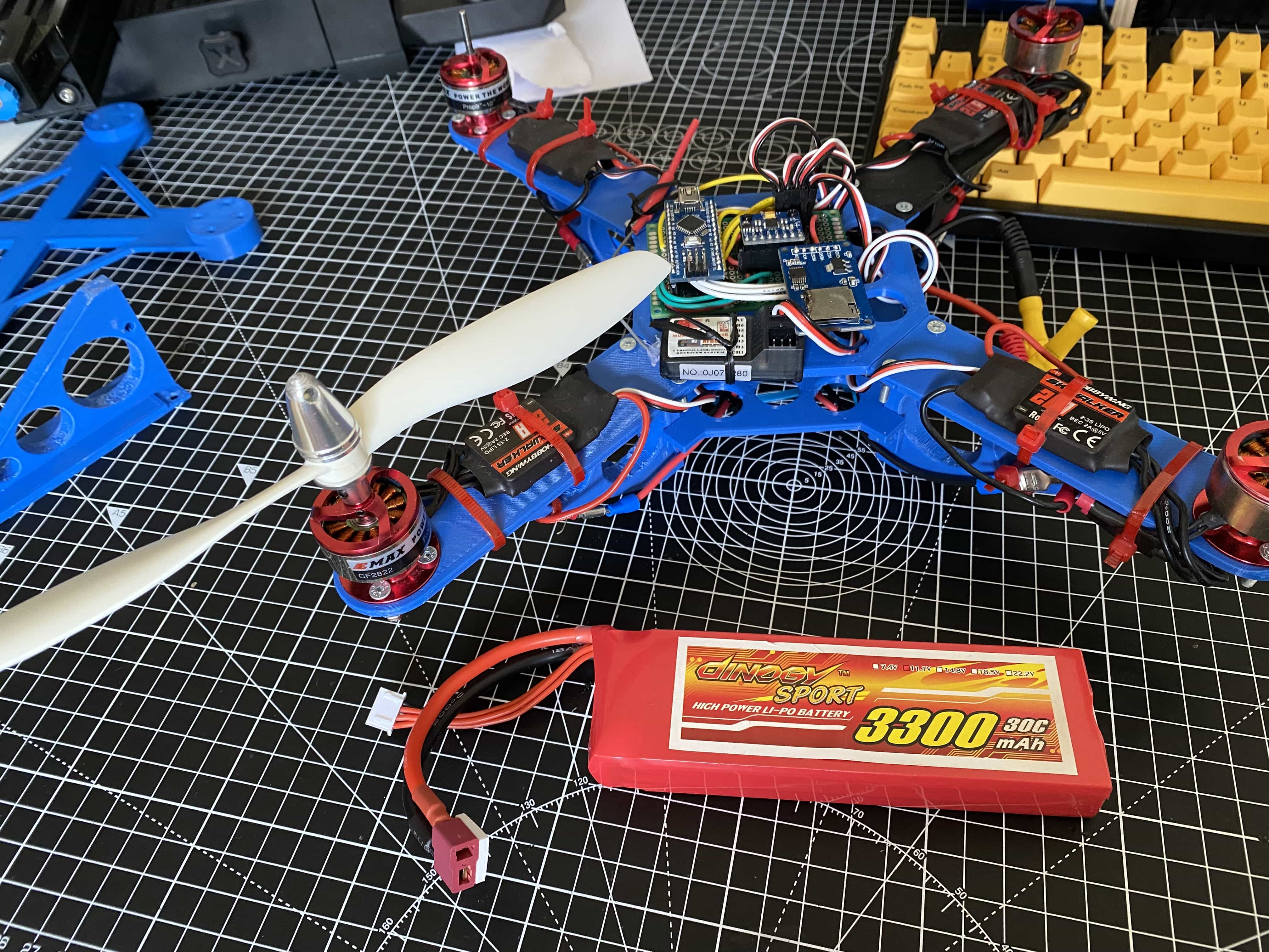
Now, this brings us to the final part, the battery. While testing out these motors previously I ran into issues with bench testing them as the motors kept tripping all of my bench top power supplies, none of them could handle the current. I was concerned at first that I was doing something wrong, but it turns out that RC vehicle batteries are build for exactly this kind of high current discharge. This might not feel intuitive, but it makes more sense when you think of flying for quad or model plane for more like 10 minutes rather than an hour straight, that's the trade off.
I'm going to talk about Lithium Polymer (LiPo) batteries in specific here as they are probably the most common for RC these days. When we talk about LiPo batteries, we usually talk about two values, the "S" value and the "C" value. The "S" value is pretty easy, LiPo batteries are made of of cells that are connected together. These cells generally have the same voltage (3.7V), so the number of cells or "S" value denotes the total battery voltage. A "3S" battery will have a voltage of 11.1V (3.7 x 3 = 11.1). That brings us to the "C" value of a battery, which is more complicated. Batteries will usually have a "C" value and another capacity rating given in the units of mAh (milli-amp-hours). This is the amount of current the battery could supply continuously for an hour. Along with the continuous discharge rating, the "C" rating defines what current is safe to draw from this battery at any one time. For example, my ECS units are rated at 20A continuous current draw but can spike up to 25A (imagine sudden acceleration). I use four of these all pulling from the same power supply. At any one time, I could draw a max of between 80-100A from the battery. The battery I picked out has a current rating of 3300mAh and is a 30C battery. I'll divide by 1000 to turn milliamps into amps giving me 3.3Ah. Then we multiply this by 30 to give 99.9A. This means that my battery can handle a max of just under 100A being drawn from it. Right on the borderline of what my ECS's is rated for. In real life, my motors are only 16A, so driving four at once will possibly only draw 64A at once. I purposely over specced my ECS units and battery by a bit so as to give me some safety buffer and flexibility.
As a final note, it's worth saying that LiPo batteries can be dangerous. They can catch fire and even explode if they are treated incorrectly or pushed outside they operating ranges. You absolutely must do your homework on what your battery needs to be capable of.
Airframe Design
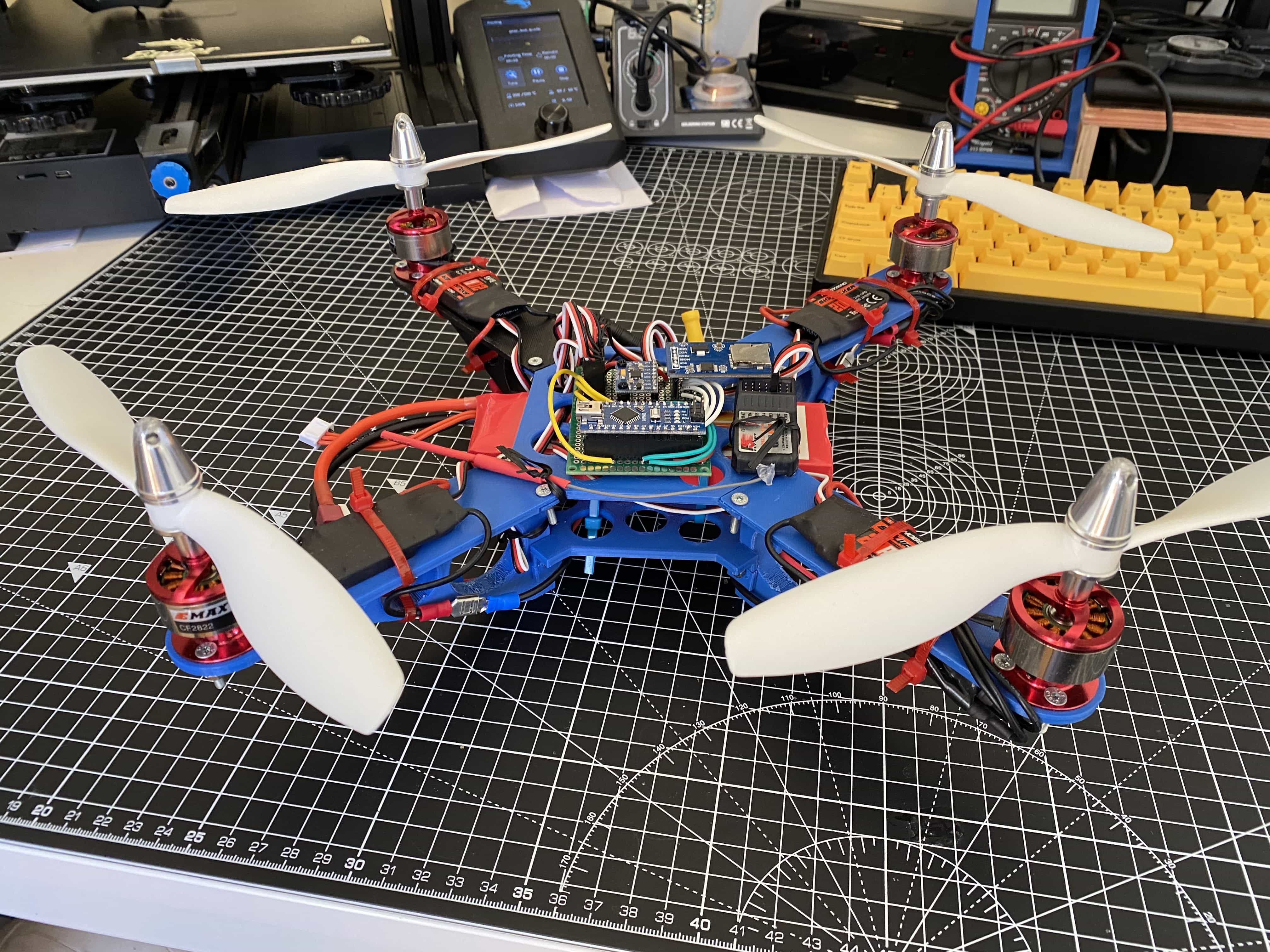
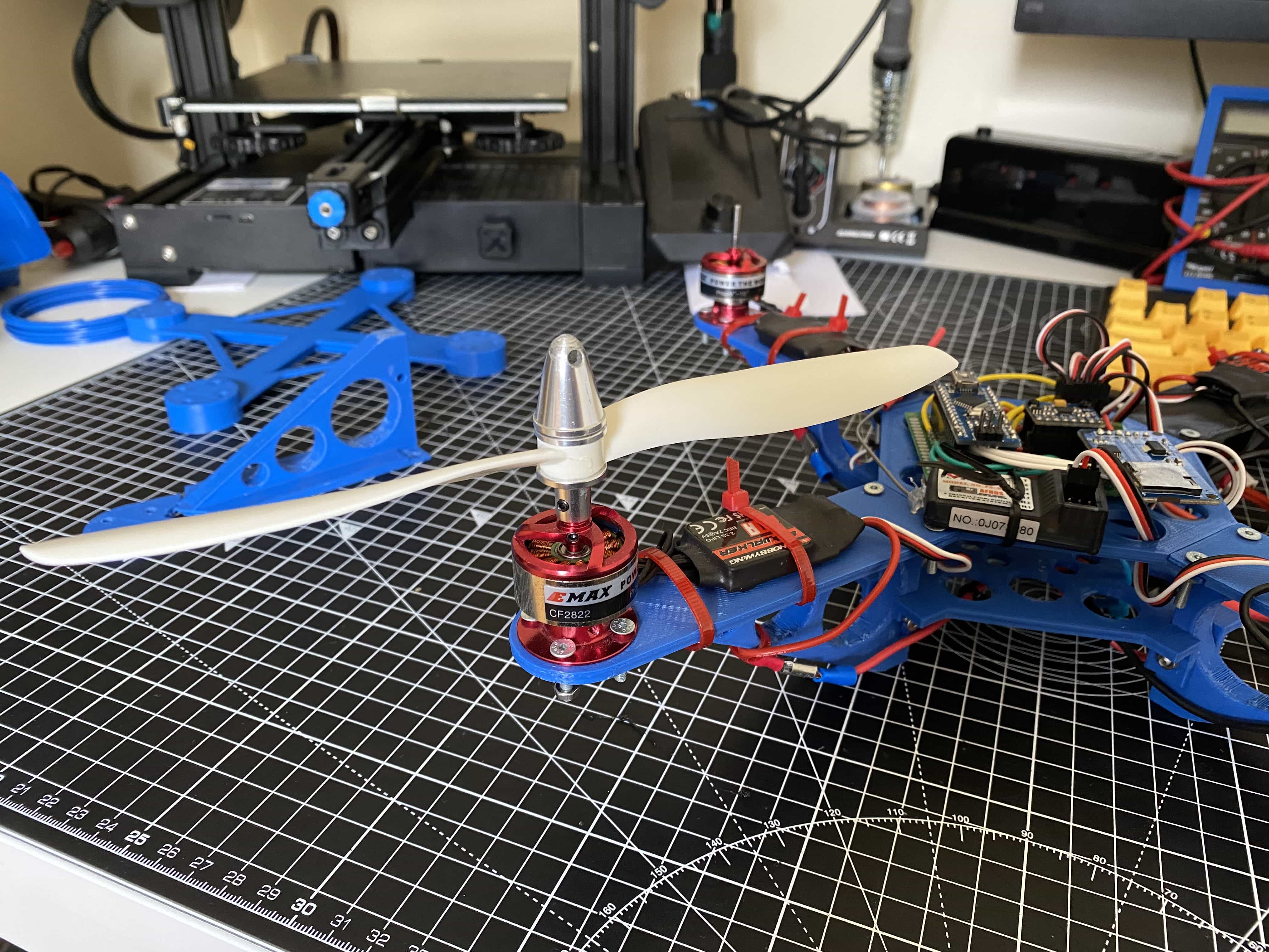
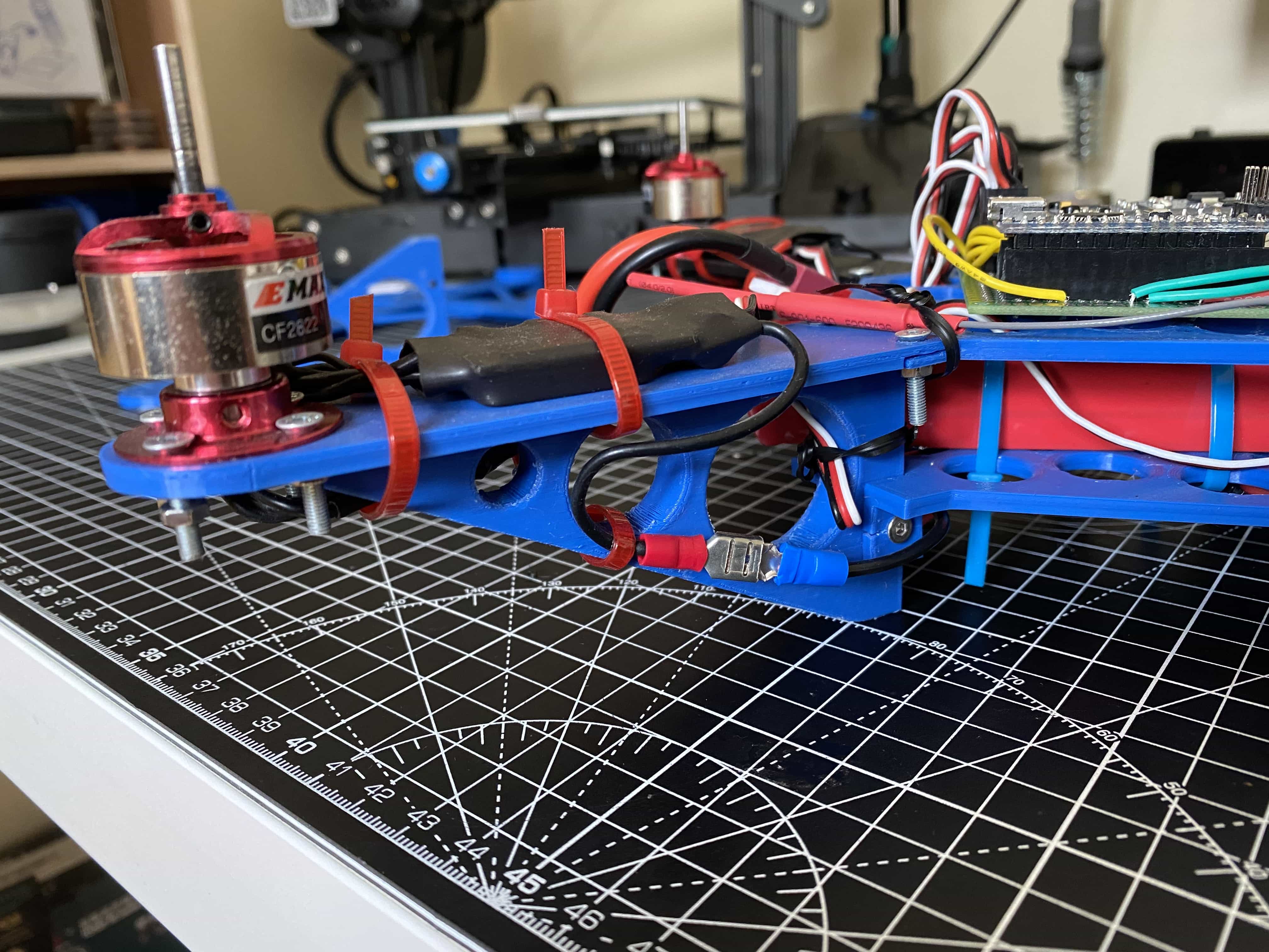
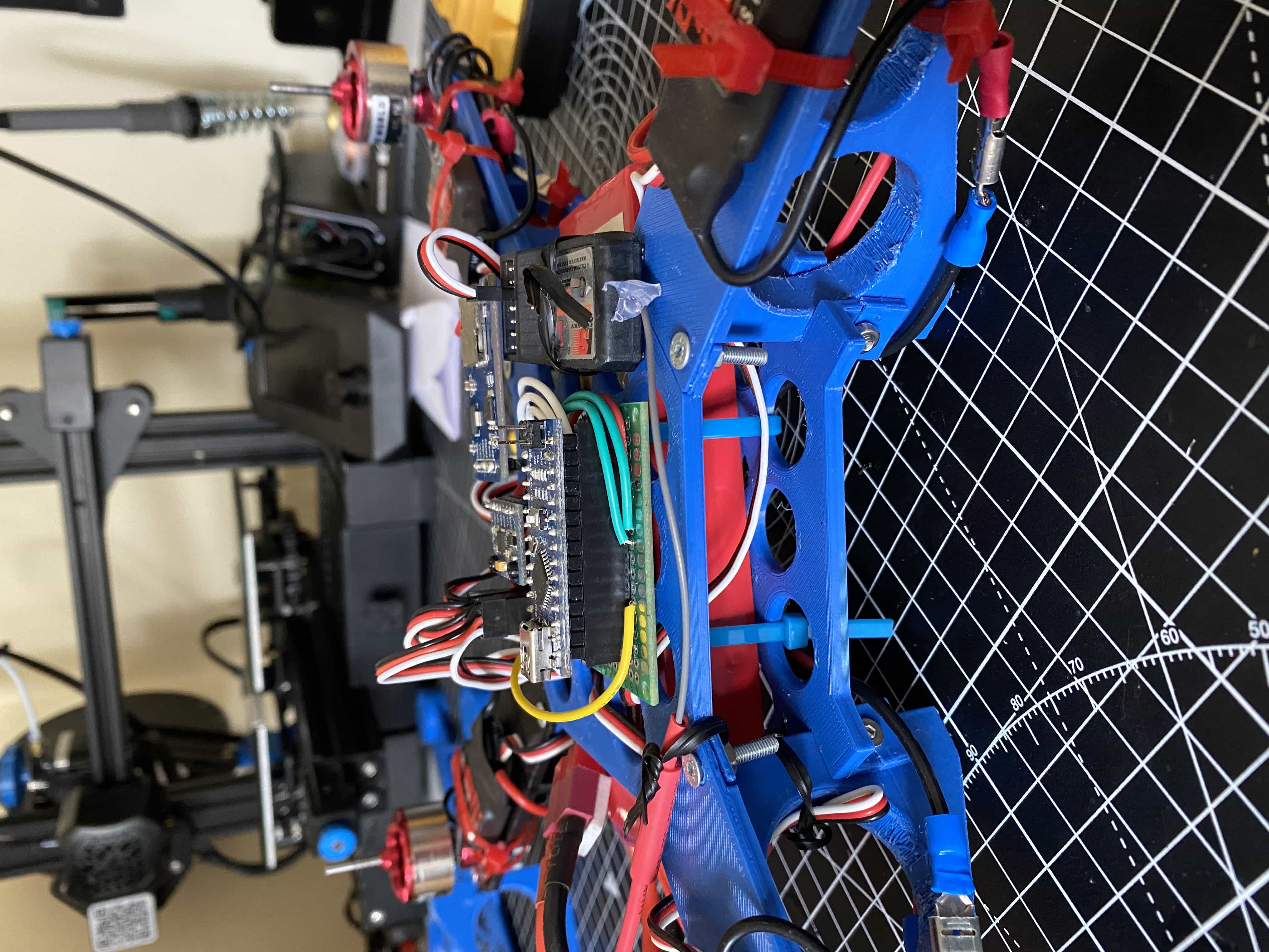
With your motors, props and battery picked, you can now try and figure out the actual footprint of the quad. My initial design for my quad started out with the small test bed platform you see below. It's just about large enough for me to mount motors, electronics, a battery and a small set of props. While it was never intended to fly, it's useful to illustrate some design concerns.
You will notice from the photo above, this frame is pretty small. I had already picked out motors that were intended to be used with fairly large props 8" props. Clearly this frame wouldn't fit those. I had also bought some small props to use here for systems testing. This wasn't strictly required, I could have spun motors with no props but I felt like I'd get more information from spinning actual props. The test bed size was mostly limited as being the largest flat thing my printer could print in one go. Despite this, it was pretty rigid and help up well while testing. It was very useful for testing all my connections, bolting down the motors and wiring it all up. Once I had it all connected up with the battery I decided to bring it outside for a "test flight". I knew it wouldn't actually fly, so I did it in the shed (it was raining at the time and I wasn't exactly worried it would suddenly take off). With that said, I still kind of thought it might at least shudder and try lift off the bench... It didn't. The props I was using were about half the size of the actual ones I wanted to use but I was really surprised at just how little lift they were giving. There are plenty of quad copters out there with a similar size to this using this size of prop, the issue really came down to the weight of the battery. To make the test bed take off, I would have needed a far smaller battery. However, that would mean my powerful motors would also need to be toned down for the current requirements. Having done this, I really did come to an intuitive understanding around the relationship between size, weight, thrust and power.
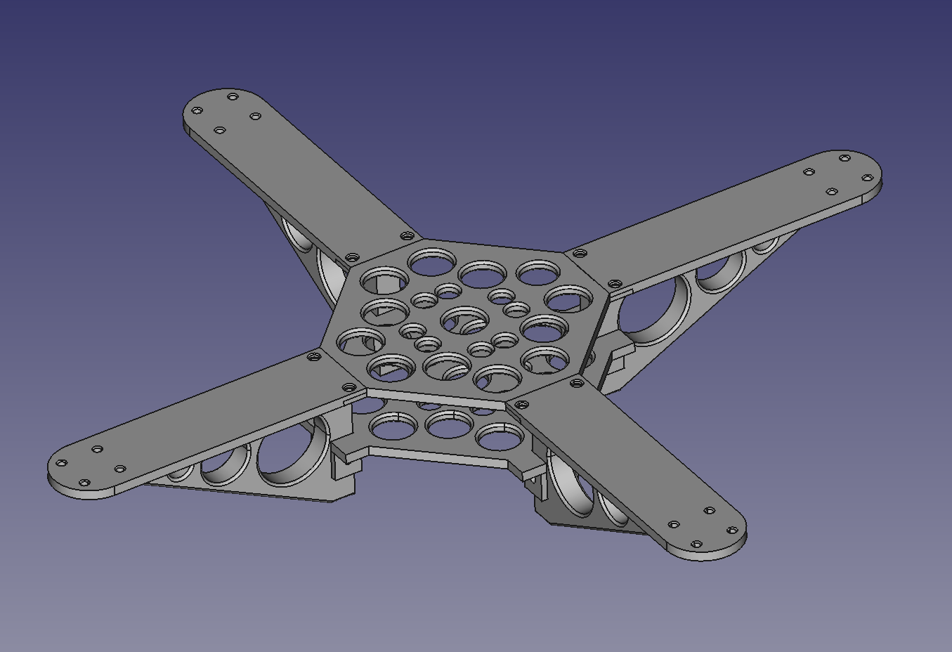
Regardless of if the test bed flew or not, it gave me all the feedback I needed on my system to start designing a full size platform that would actually fly. I'll start off by showing the final, or should I say current design of the quad (it may change in the future). I'll then go into details around the initial consideration for the design and the constraints I built it under.
Let's start with talking about the constraints of building this. The first constraint is that I wanted to make all the parts for the frame on the 3d printer. I really don't think FDM 3D printed PLA is the best material for building a quadcopter, but this project isn't about building the best quadcopter in the world, it's about building a 3D printed quad copter. While PLA might be fairly brittle, it does have some advantages for making a quadcopter. You can easily design parts to be strong and rigid while still being very light. You can also build in a certain amount of flex which comes in useful for compensating for the brittleness.
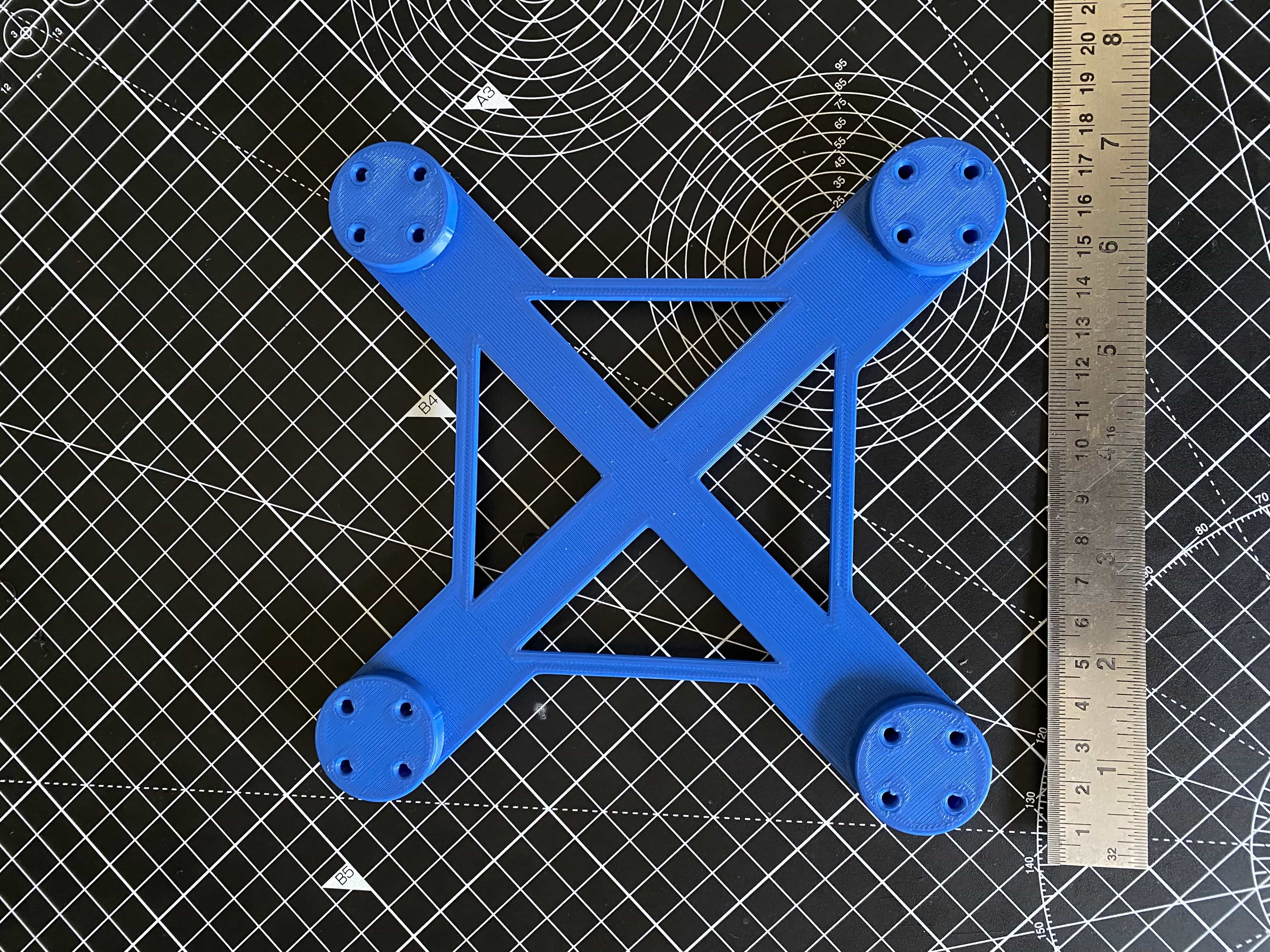
With the 3D printer being my fabrication tool, I was limited to parts with a footprint of less than 200x200mm. When you consider I had picked out to use 8" props, the minimum clearance between each motor has to be 8" or around 200mm. With this in mind and given the print bed size of my printer. I decided the quad should be constructed with each arm or strut being printed as one piece, with four identical parts bolting to a central hub to form the body. I decided that each strut would be a motor mount as well as a leg for the quad to stand on while on the ground. This decision made the struts fairly bulky but this actually turned out to be desirable. While testing it was found that in most crashes, it's usually a single strut which takes the brunt of the impact. In tests with less bulky struts, they would shatter fairly easily with minimal impact.
Continuing the discussion of the struts, symmetry was an important consideration here. In general, quadcopters need to be well balanced. Symmetrical parts are by their nature well balanced, so there is a win straight away. Another win comes in the ease of replacing them with spare parts. As each strut is the same, you can have several replacements printed at any time. If any strut breaks, you can just stick in any spare you have. Ease of replacement was also a consideration for the attachment mechanism for the struts. They are held on by only 3 easy to access bolts making it quick and easy to replace a broken one. One final point about the struts; you might have noticed the not so subtle holes cut out of them. These holes are probably not what you think they are for. You might thing that they are for weight reduction, but they really don't change the final weight all that much. As the entire quad is a prototype, their purpose is actually to be tie points. I added loads of holes all over to allow things to be cable tied down to experiment with mounting and weight distribution etc. This is also the reason for the holes in the central hub.
The final piece to design was the central hub. Given I had just designed a very robust structure for the struts, this made me consider if the central hub really needed to be strong on it's own. I decided to take a gamble and design the hub with something of a "tensegrity" model (kind of). The idea being that the hub it's self is made of only two thin and light parts floating on a few bolts attaching to the struts. In this design, the quad it's self is really only strong when fully assembled. Removing even one of the struts leaves the entire structure very flimsy. However, once bolted together the frame is surprisingly strong. An added benefit of this approach also meant that I could print the hub parts relatively thin. This means that they have some flex particularly around the mounting points. This helps absorb shock from crash impact. Amazingly, I have replaced each strut on my quad at this stage from crashes, but I have never had to replace either hub piece (which would be a pain).
I put together a short video if you would like to see some slow motion footage of the drone crashing, you can find it here on my Youtube Channel.
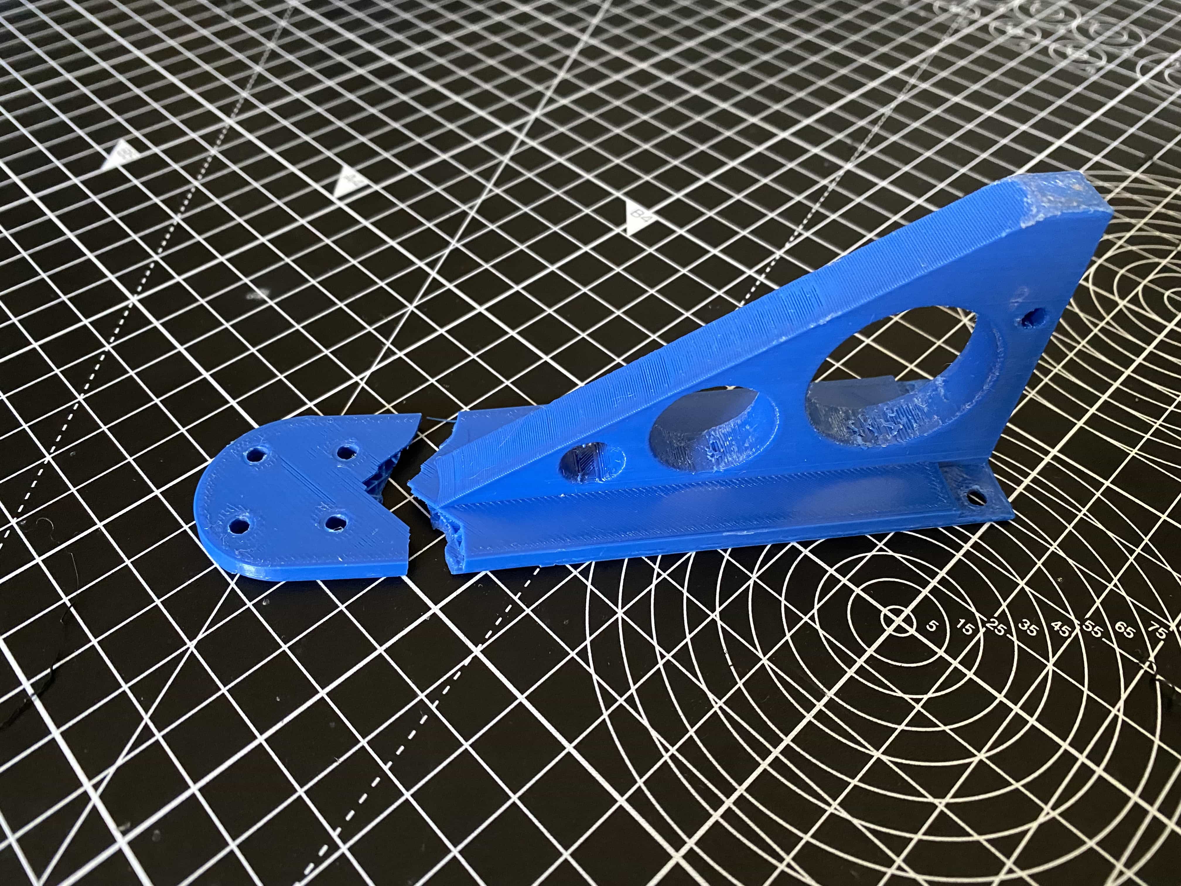
There are a few definite improvements to be made in this mechanical design. Up to this point, the entire structure has been designed as a prototype for an entire system. I am now coming to a point where all of the electronics and flight controls are more or less finished. Once I am happy with things at a certain point, I plan to rework the mechanical design and incorporate a few improvements I have come up with. As a final note, I have already implemented one improvement to the mechanical design. If you look below, you will see and old broken strut. During many early flight tests that involved crashes (...that means all of them), the motor mount would snap straight off the end of the strut if it flipped and landed on a rotor. It's pretty clear that there was not enough support out to the end of the strut. I have improved the design now so that this is less frequent, but this remains the single largest point of failure for violent crashes. It will be the first design flaw I address in future iterations. If you decide to make your own version of this, I apologise if this happens, but I will be fixing it eventually.
Wrapping Up
I hope you found this an interesting and useful read. This is only the first in a series I am planning on designing and building this quadcopter. In the next article I plan to talk about the electronics, software and control theory behind the quad. However, before I do that, I need to make it fly a little better 😬. In the meantime, if you like my design and would like to take a crack at 3D printing your very own, you can download all the STL files required to print your own here.
Happy Building and Flying - IanIf you enjoyed reading this article and would like to help funding future content, please consider supporting my work on Patreon.